| 
    This task shows
    you how to create geometry by projecting
      one or more elements onto a  support. The projection may be normal or along a direction. 
      You can project:
      
          | a point onto a surface or wireframe support |  
          | wireframe geometry onto a surface support |  
          | any combination of points and wireframe onto a surface support. |  
       
     | 
  
  
      | 
    Generally
      speaking, the projection operation has a derivative effect, meaning that
      there may be a continuity loss when projecting an element onto another. If
      the initial element presents a curvature continuity, the resulting
      projected element presents at least a tangency continuity. If the initial
      element presents a tangency continuity, the resulting projected element
      presents at least a point continuity. | 


  | 
    
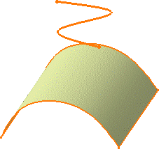
       Open the Projection1.CATPart document. 
     | 
  
  
      | 
    
      
        - 
          
Click the Projection icon   .  
       
    
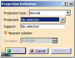
      The Projection Definition dialog box appears. 
     
     | 
      | 
  
  
     | 
        | 
     | 
  
  
     | 
    
      
        - 
          
Select the element to be Projected.  
       
      
        You can select several elements
        to be projected.  In this case, the Projected field
        indicates: x elements 
       
     | 
      | 
  
  
     | 
    
      
        - 
          
Select the Support element.
          
       
     | 
     | 
  
  
     | 
    
      
        - 
          
Use the combo to specify the direction type for 
          the projection:  
       
      
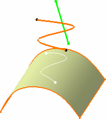
          | Normal: the projection is done normal to the support element. |  
       
     | 
      | 
  
  
     | 
    
      
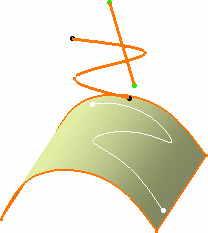
          |  Along a direction: you need to select a line to take its
        orientation as the translation direction or a plane to take its normal as the translation direction. |  
       
    
        You can also specify the direction by means of X, Y, Z vector
        components by using the contextual menu on the Direction field. 
       
     | 
      | 
  
  
     | 
       | 
  
  
     | 
    
      
        - 
          
Click OK to create the projection element.  
       
 The projection (identified as Project.xxx) is added to the specification
        tree.  
     | 
  
  
     | 
    
      
          | 
           Whenever several projections are possible, you can select the Nearest
        Solution check box to keep the nearest projection.  |  
       
     | 


         | 
    
       The following capabilities are available:
      Stacking
      Commands and Selecting
      Using Multi-Output.  | 
  
  
     | 
    Multi-selection
      is available. Refer to Editing
      a List of Elements to find out how to display and manage the list of selected
      elements. | 


  |