- SYNOPSIS
- Poor adiabatic efficiency.
- High cost of construction.
- High cost of installation in the system.
- CONCLUSIONS
- Brasz, J. J. Performance Characteristics of Two-Phase -Flow Turbo-Expanders used in Water-Cooled Chillers International Conference on Industrial Compressors and their Systems, City University, London, IMechE Publication Sept 13-15, 1999.
- Smith, I. K. and Aldis, C. A. Lysholm screw expanders in place of throttle valves in large heat pump and refrigeration systems, Proc Meeting of Commission E2, Stockholm, August 29-31,1990.
- Smith, I. K. and Stosic, N. R. The Expressor: An efficiency boost to vapour compression systems by power recovery from the throttling process. AES-vol.34, Heat pump and refrigeration systems design, Analysis and applications, ASME 1995, pp. 173-181.
- Taniguchi, H, Giedt, W. H, Kudo, K, Kasahara, K, Ohta, J and Kawamura, K. Energy-conserving heat pump-boiler systems for district heating. Proceedings of Eighteenth Intersociety Energy Conversion Conference, 1983, v4, pp. 1862-1868.
- Smith, I. K. Stosic, N and Aldis, C. A. Development of the trilateral flash cycle system Part 3: the design of high efficiency two-phase screw expanders. Proc Instn Mech Engrs, Part A, 1996, 210(A2), 75-93.
- Smith, I. K and Stosic, N. R. US Pat 5,833,446, November 10th 1998.
- Stosic, N. R. Plural screw positive displacement machines. Int Pat Application No: WO 97/43550, 20 November 1997.
- Stosic, N, Smith, I. K, Kovacevic, A and Aldis, C. A. The design of a twin-screw compressor based on a new rotor profile. Jrnl of Engng Design, v.8, n.4, 1997, pp389-399
- Stosic, N, Smith, I. K, Brasz, J. J and Sishtla, V. The performance of a screw compressor with involute contact rotors in a low viscosity gas-liquid mixture environment. VDI Berichte NR. 1391, 1998, pp 279-292.
- Jacobson, B. Ball-bearing lubrication in refrigeration compressors. Proc 1996 International Compressor Conference at Purdue, v1, Purdue University, West Lafayette, IND, USA, July 23-26, 1996, pp 103-108.
2. INTRODUCTION
R134a has advantages as a refrigerant, in that it has no atmospheric ozone depleting tendencies. However, due to relatively large throttling losses, its use in chiller applications results in a reduction in the C.O.P of some 6% relative to R11. As already shown [1] this disadvantage can be largely overcome by replacing the throttle valve by a turbo expander, the output of which can be used to reduce the compressor work input. The layout of this is presented in Fig. 1.
The use of a twin screw expander as a throttle valve replacement has been proposed or tried by several investigators [2-5] but although it has long been known that such a machine can recover power from two-phase expansion processes, the high cost of its installation hardly made its adoption worthwhile. The most significant factors responsible for this were:
Another requirement for achieving high adiabatic efficiencies is the maintenance of near equilibrium between the liquid and vapour during the two-phase expansion process. To achieve this, the working fluid must absorb as little lubricating oil as possible and this led to the need for two features which raised the cost of construction.
The oil lubrication system for the bearings had to be pump driven and separated from the expander working chamber by internal shaft seals of which various types have been tested. Apart from their high cost, the inclusion of the seals greatly increased the unsupported length of the rotors and led to the need for thicker rotor shafts and a larger casing which further raised the manufacturing cost. Moreover, the refrigerant in the expander working chamber has a liquid content of approximately 80% by mass and, unlike gas, this absorbs oil very readily. Hence, bearing oil leakage rates into the working chamber, which would be acceptable in gas compressors, led to unacceptably high levels of oil contamination of the working fluid in two-phase screw expanders with the seal types tried out.
Various modes of installing the expander in the system have been proposed. These included; coupling the expander directly to the main compressor drive shaft, coupling the expander to an electrical generator and coupling the expander to a matching set of rotors in which part of the expanded vapour is recompressed [3].
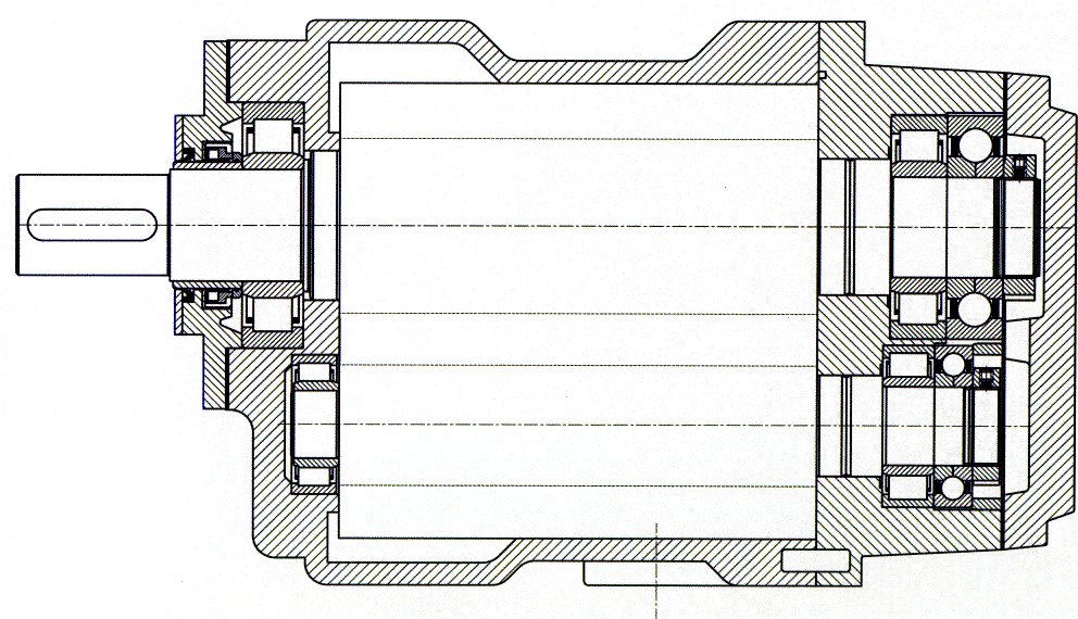
Fig. 2 The expander layout
The first arrangement requires an electrical generator to be included with further loss of output through it, while both the first two proposals require a slide valve to be included in the expander in order to maintain variable flow at constant speed. The last arrangement, termed an "expressor" by the authors, could run as a self regulating device at any speed but effectively constitutes two machines in one casing.
A final decision on which type of installation would be most suitable
for installation of a screw expander in a chiller unit was not made. However,
it was considered to be a worthwhile exercise to design, construct and
test a simple demonstration unit without a slide valve in order to determine
how well the design principles demonstrated in [7,8] would work when applied
to a 500 ton chiller unit operating with R134a as the working fluid and
to simplify the design as much as possible in order to minimise its cost.
The target set for this exercise was to achieve adiabatic efficiencies
in excess of 70%.
- 3. DESIGN DETAILS
It was decided that with these rotors it would be possible to dispense with the timing gear and rely on the presence of liquid refrigerant to act as a coolant should any heat be generated by rotor contact. This was first checked by using the same profile rotors in an oil injected compressor in which water was used as the injected fluid [9]. This ran successfully for 150 hours without any detectable rotor wear at higher pressure differences than were required for the expander.

Fig 3. A view of the expander, as installed in the test rig
Advances in rolling element bearing design [10] led to the decision to use liquid refrigerant as the bearing coolant and thereby completely eliminate oil from the expander system. Internal shaft seals then would not be required.
These assumptions led to the design of a machine with rotors of 5/6
configuration, a male rotor diameter of 127.5mm and an L/D ratio of 1.65.
The built in volume ratio was set at 2.85:1 in order to achieve an overall
volume ratio of 12.3:1. Only one external shaft seal is required, of the
type used in refrigeration compressors, and as shown in Fig. 2, the layout
is very simple.
- 4. EXPERIMENTAL ARRANGEMENTS
The rig was originally designed and constructed in 1984 and before use on the expander described in this paper, it was extensively refurbished, especially with regard to the data acquisition, display and processing. This included the use of four piezzo resistive pressure transducers located within the expander to record and display how the pressure changes within the expander as a function of rotational angle. The mode of screen data presentation employed is shown in Fig 5.
Fig. 4 City University expander test rig
A key requirement of the experimental programme was to simulate an R134a expansion under chiller design conditions as closely as possible. This involved the working fluid being admitted to the machine as subcooled liquid; a process not previously attempted. The most rigorous replication when using R113, would be to keep the expander inlet and exit pressures the same as in a chiller operating on R134a with an equal amount of subcooling at the inlet. At the design point, this corresponded to R113 entering the expander at a pressure of 8.45 bar and a temperature of 126oC and leaving at 3.76 bar with a corresponding saturation temperature of 93oC. With R113, the volume expansion ratio would then be 20% greater and the mass flow 15% higher than with R134a, the larger mass flow being mainly due to the higher liquid density of R113. Up to the time of writing, the analytical model for predicting the expander performance would not solve if subcooling at the inlet was assumed. This is because it is based on the non-steady flow energy equation applied to a variable volume and small changes in volume induce instantaneous phase changes. Computer simulations of the expander performance with both fluids were therefore carried out on the assumption of saturated liquid at the expander inlet. The results showed that under these conditions, the power output with R113 would be approximately 12% greater and the adiabatic efficiency about 2% less than when using R134a. These differences were considered to be sufficiently small to make the R113 test results meaningful, bearing in mind that the installation of a two-phase expander of 70% adiabatic efficiency would increase the overall COP of the chiller unit by approximately 7%.
In view of the very small temperature and specific enthalpy changes associated with the planned tests, every effort was made to ensure the accuracy of the pressure, temperature, mass flow, speed and torque measurements and all instruments were repeatedly calibrated against instruments with recognised standards certificates. Despite this, it was almost impossible to obtain temperature measurements at the exit without some small degree of superheat compared to saturated values at the measured pressure. It was therefore concluded that the fluid was leaving the expander in a non-equilibrium condition with a small amount of liquid superheat.
Fig. 5 A screen print
Nonetheless, in estimating the adiabatic efficiency of the expander
it was assumed that the ideal condition of the fluid at exit was with the
liquid and vapour in thermodynamic equilibrium since this is the most rigorous
criterion applicable.
- 5. TEST RESULTS AND THEIR INTERPRETATION
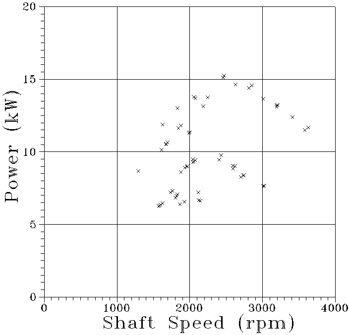
Fig. 6 Power output variation with rotational speed
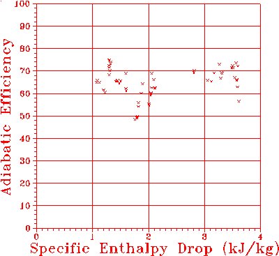
Fig. 7 Power output variation with specific enthalpy drop
An error analysis was carried out on the test results. These showed the following:
Measurement errors of expander inlet pressure had a negligible effect
since the fluid was subcooled. Inlet temperature measurement errors produce
an adiabatic efficiency error of 5% per 1oC. Exit pressure measurement
errors produce an adiabatic efficiency error of 5% per 0.1Bar. Errors in
adiabatic efficiency estimates due to
errors in fluid flow and torque measurements would each be of the order
of 1%.
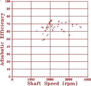
Fig. 8 Adiabatic efficiency variation with rotational speed
Overall it is estimated that the uncertainty in the derived results is of the order of ±3% or approximately ±2 percentage points at an estimated adiabatic efficiency of 70%. This is too small to affect the results shown in Figs. 6 to 9 radically.
Graphical display of results permits an output variable to be shown as a function of two input variables. This is sufficient for unambiguous presentation of single-phase expansion processes of fixed pressure ratio. In the case of two-phase expansion there is an additional variable of inlet fluid quality, which is not displayed. Also it was extremely difficult to control all the variables while maintaining a constant pressure ratio. These factors are the main cause of the apparent scatter of the test points.
As may be seen, a substantial number of test points were obtained at
adiabatic efficiencies of over 70%. These amounted to approximately 28%
of the total. To the best of the authors knowledge these are the highest
values ever achieved in any type of two-phase expander and in this respect
the performance predictions were realised. The corresponding mass flow
measurements were 20-40% less than those predicted from the assumption
of saturated liquid admission. Test results of two-phase expansion through
a nozzle [1] showed that in steady flow, subcooling increased the mass
flow rate and this is in agreement with qualitative reasoning on how the
machine swallowing capacity should be affected. A convincing explanation
for this apparent anomaly in screw expander performance has not yet been
found and investigations are continuing on how to resolve it as well as
finding a means of analysing the transition from subcooled liquid to two-phase
mixture during discrete system changes.
Fig. 9 Adiabatic efficiency variation with specific enthalpy drop
After completion of the construction of the expander, cost estimates
were obtained for the manufacture of such a machine in small batches.
REFERENCES