|
1
|
|
|
2
|
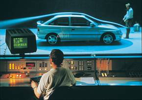
- Inženjerski dizajn (Engineering Design)
- CAE/CAD/CAM:
- Uvod, Struktura Hardware i Software
- Modeli u CAD, IRP, Baze podataka, Interface
- Pre i Post Procesori
- CATIA i MDT
- CFD/CCM - Metoda konačnih volumena
FEM - Metoda
konačnih elemenata
|
|
3
|
|
|
4
|
|
|
5
|
|
|
6
|
|
|
7
|
|
|
8
|
|
|
9
|
|
|
10
|
|
|
11
|
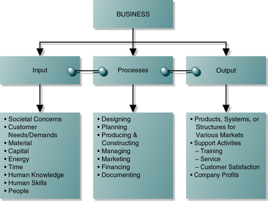
- Engineers:
- Provide ways to meet needs and wants of society
- Invent or design new products and processes
- Improve existing products and processes
- Work in teams throughout the design process
- Bottom line:
|
|
12
|
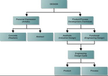
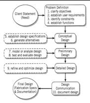
- Design is:
- Systematic Process by which solution to the needs of humankind are obtained
and communicated
- Essence of Engineering
- Structured problem solving activity
- Engineering Design Process is:
- Multidisciplinary task which contains:
- Technological factors
- Social factors
- Team iterative work
|
|
13
|
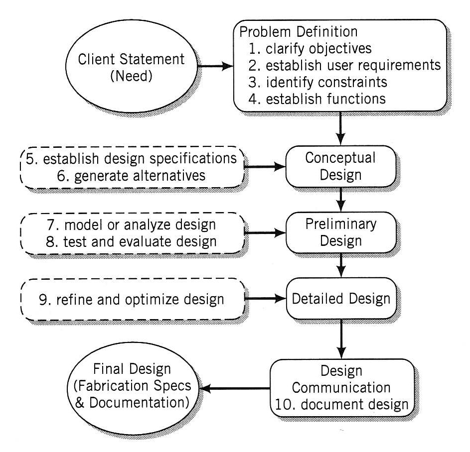
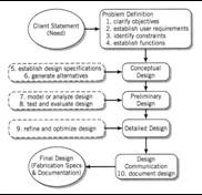
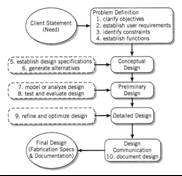
- Engineering design process
an iterative decision making activity, to produce plans by which resources
are converted, preferably optimally with due consideration for
environment into systems and devices (products) to meet human needs.
(Woodson.T.T )
- Mechanical design process
is the use of scientific principles and technical information
along with innovations, ingenuity or imagination in the definition of a
machine, mechanical device or system (product) to perform pre specified
functions with maximum economy and efficiency.
(Engineering Design Council, UK)
|
|
14
|
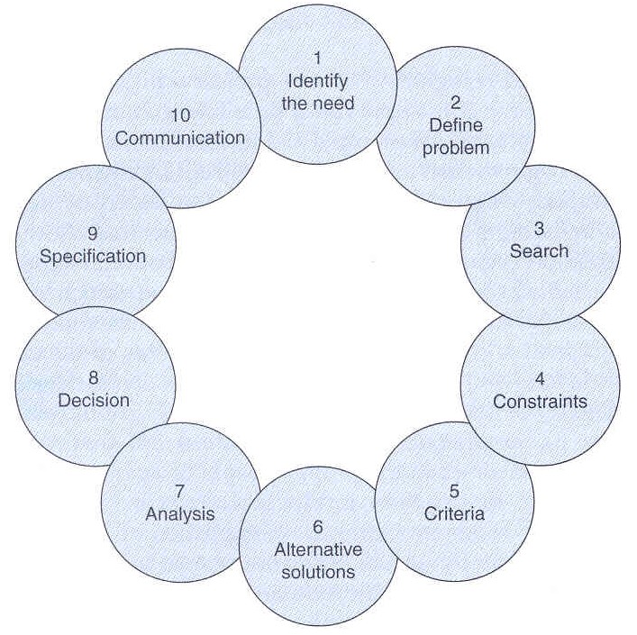
- Design – structured problem solving activity
- Process – phenomenon of making changes to achieve a required result
- Design Process – cyclic continuous activity
|
|
15
|
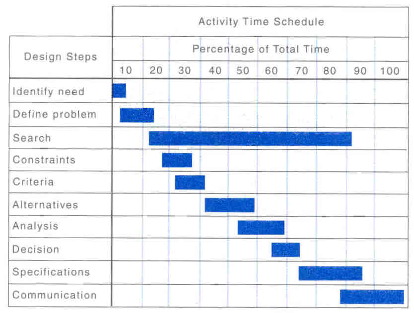
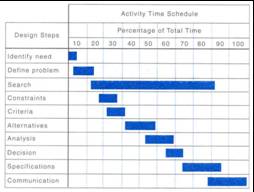
- All projects have time constraints
- An adequate planning leads to a satisfactory project finish
|
|
16
|
|
|
17
|
|
|
18
|
|
|
19
|
|
|
20
|
|
|
21
|
|
|
22
|
|
|
23
|
|
|
24
|
- The objectives tree method is an approach to transform vague design
statements into more specific customer requirements
- Make vague statements more specific by asking:
- What is meant by that statement?
- Other useful questions to ask when expanding and clarifying design
objectives:
|
|
25
|
- Three step procedure:
- Prepare a list of design objectives
- Order the list into sets of higher-level and lower-level objectives
- Draw a tree of objectives, showing hierarchical relationships and
interconnections
|
|
26
|
- This can be done by:
- Talking with (interviewing) customer
- Thoroughly reading any written design statements and requirements
- Take vague statements and make them clearer by asking “what is meant by
this statement”
|
|
27
|
- Group the statements into related topics using an affinity diagram
|
|
28
|
- Copy design objectives to post-it® notes
- Place one on a board
- Compare next objective card to the first
- If different, begin a new column
- If similar intent, place under the first column
- Repeat for all design objective cards
- Result: Objectives sorted by similar statement
- Within each column there may be levels of objectives
- Lower-level objectives answer the question “How?”
- Higher-level objectives answer the question “Why?”
|
|
29
|
- The Objectives Tree diagram looks like an “upside-down” tree
- The overall objective of the tree is at the top
- Underneath it, branches
break the objective
into more detailed
objectives
- Can have many
levels and
interconnections
|
|
30
|
- The objectives tree diagram may alternatively be drawn on its side
- Example: Car door
|
|
31
|
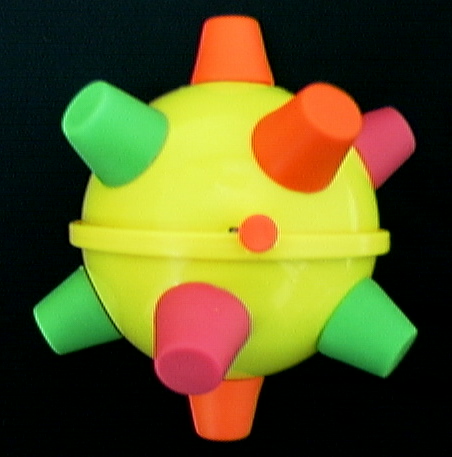
- As a team, generate a list of objectives for the bumble ball toy
- Complete the affinity method for ordering the objectives in class
- Draw an objectives tree for the bumble ball
|
|
32
|
- Objectives are qualities the
object should have
- Clients tend to speak in terms of objectives
- The Functions are what the product does without considering any
particular solution
- Engineers tend to speak in terms of functions
- Identifying the basic functions an object does, and then determining
solutions for these functions separately, leads to better solutions for
the overall problem
- Two levels of functions:
Overall functions and Sub-functions
- A product function is defined in
a block diagram known as a Functional Model
|
|
33
|
- It places the emphasis on what has to be accomplished rather than how
- It makes clear the various sub-systems or functions that need to be
solved in order to solve the entire problem
- Enhances the creativity of the design team by allowing them to focus on
one sub-function at a time
- Sub-functions may be derived from objectives tree (or customer needs)
|
|
34
|
- Functional model
- It is a picture, a graphical representation
- The overall function of a product is sub-divided into smaller, more
elemental (i.e. atomic) sub-functions
- The sub-functions are connected by the flows on which they operate
- Sub-functions
- Simpler expressions of part of the product’s overall function
- Expressed in verb-object form at a consistent level of detail
|
|
35
|
|
|
36
|
- A functional description is a combination of a function (verb) acting on
a flow (object)
- Function - the operation that the product performs on a flow or a set
of flows to transform it from its input state to its output state
- Flow - a material, energy or signal that is used by or affects the
product
- Think of a flow as anything that is input to the product or an output
of the product
|
|
37
|
- Functional description form:
Function (Verb)–Flow (Object)
- Examples of functional descriptions
|
|
38
|
- Step 1: Create a “black box” model of the product
- State overall function of product
- Use your objective tree high level objectives to help determine the
overall function
- Identify input and output flows
- Possibly related to lowest level objectives
|
|
39
|
- Step 2: Break down overall function into sub-functions
- Follow each input flow through the product and imagine what function
the product performs on the flow
- The Zen approach: BE the flow
|
|
40
|
- For the flow of electrical energy, what is its associated sub-functions?
|
|
41
|
- Flow of the user mechanical energy,
- what are associated
sub-functions?
|
|
42
|
- Step 3: Connect the sub-function chains together
- This may require additional sub-functions or connecting flows
|
|
43
|
- Step 3: Connect the sub-function chains together
- This may require additional sub-functions or connecting flows
|
|
44
|
- Step 3: Connect the sub-function chains together
- This may require additional sub-functions or connecting flows
|
|
45
|
- Step 4: Define the system boundary
- This ensures that only product sub-functions are considered for future
design work
|
|
46
|
- Step 5: Identify appropriate components to perform sub-functions and
their interactions
|
|
47
|
- What’s the difference between
objectives and functions?
- Objectives tell us what the final product will “be”, what qualities it
will have
- Functions tell us what the object will “do”, without regard to any
particular form
- Functions will always relate input to output
- Functions capture the transformation that takes place between input
and output
- Though the difference may seem subtle, it is a very important
distinction
|
|
48
|
|
|
49
|
The Performance Specification Method
|
|
50
|
- After the objectives of what the product must do are set, its performance
has to be specified
- It is formulating Engineering Specifications
- Engineering Specifications:
- Specify a target range for performance
- Define required performance, not the solution
- Provide a way to evaluate proposed solutions
|
|
51
|
- Three ways to formalize what the user wants in terms more suitable for
engineering design and analysis
- Prescriptive specifications (or constraints)
- Specify values for attributes of the designed product/process
- Ex.: The ladder step length can not exceed 20 in.
- Procedural specifications
- Identify specific procedures for calculating attributes or behavior
- Ex.: Maximum bending stress on a step is computed from smax = Mc/I and the
step is safe if smax
does not exceed sallow
- Performance specifications
- Identify performance levels that signify the desired functional
behavior has been achieved
- Ex.: A step on a ladder is safe if it supports an 200 kg load
|
|
52
|
- Step 1: Compile specifications
- Use the functional model as a starting point
- For each sub-function, write an associated specification (independent
of any particular solution)
- For example:
|
|
53
|
- Support for Step 1: Standard categories for searching for specifications
|
|
54
|
- Step 2: Sort the engineering specifications by type
- Prescriptive (constraints)
- Procedural
- Performance
- Step 3: Quantify each engineering specification
- Engineering specifications should be quantified
- Express specifications as a range with limits or specific values (in
the case of constraints)
- Quantifying may lead to more detailed specifications
- For example:
|
|
55
|
- Step 4: Determine testing/verification approaches
- Identify what procedure your team will use to check that each
specification is met
- State when the test or verification will occur in project timeline
- Examples (from disc launcher):
|
|
56
|
- Step 5: Compile elements of engineering specification into a single
document
|
|
57
|
- Step 6: Evaluate and update specifications as needed throughout the
design project
- Make sure identified constraints are not too restrictive as to
eliminate a better solution
- If specifications are updated, indicate so in the date column of the
sheet
|
|
58
|
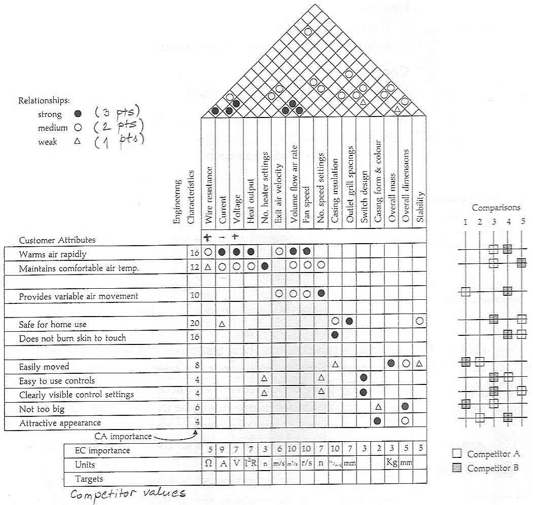
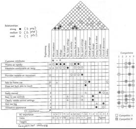
- The Quality Function Deployment Method
- or
- Design Matrix
- or
- House of Quality
|
|
59
|
- After the Function is analysed,
designer has
to define Engineering characteristics of a product.
- Designer defines ® ® ® ® Physical properties
- Physical properties determine® Engineering
characteristics
- Characteristics determine ® ® Product attributes
- Product attributes satisfy ® ® Customer needs and requirements
- Marketing people require Þ desirable
attributes
- Designers and engineers Þ engineering
speak in terms of characteristics
|
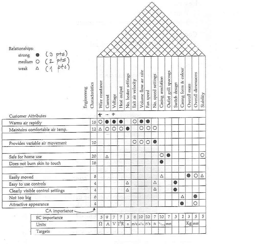
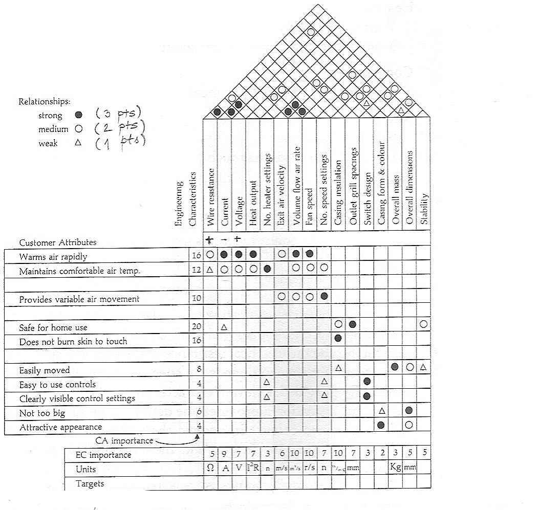
|
60
|
- QFD has background in Japanese design science.
Concerned with the translation of customer requirements into engineering
characteristics.
- Identify customer requirements in terms of product attributes,
- Determine the relative importance of attributes,
- Evaluate the attributes of competing products,
- Draw a matrix of product attributes against engineering
characteristics,
- Identify the relationship between engineering characteristics and
product attributes,
- Identify relevant interactions between engineering characteristics,
- Set target figures to be achieved for the engineering characteristics.
|
|
61
|
- Identify customer requirements in terms of product attributes
- Customer requirements should not be re-interpreted but
only described in terms of product requirements.
- Determine the relative importance of attributes,
- Rank-ordering methods can be used to help determine
the relative weights of each attribute.
- To do that systematically compare pair of objectives, one against the
other.
- Objectives A B C D E row total
A - 0 0 0 1 1
B 1 - 1 1 1 4
C 1 0 - 1 1 3
D 1 0 0 - 1 2
E 0 0 0 0 - 0
- Evaluate the attributes of competing products,
- Performance scores for competing products and the own product
should be listed against the set of customer requirements
|
|
62
|
- Set target figures to be achieved for the engineering characteristics.
- These information are obtained from the comparison with competitor
products or from trials with customers. These can be set comparative
to competitors.
|
|
63
|
|
|
64
|
- Previously, problem was clarified by use of four design tools
- Objectives Tree: A way to
analyze customer needs and to group them logically
- Functional Model: An engineering
first step at thinking about the general functions that the device must
be able to do
- Engineering Specifications: A first step to specifying performance of the product or process
to be designed
- The Quality Function Deployment Method – Design Matrix:
Tool which helps to specify what the product must achieve and
the criteria by which the alternative solutions will be judged.
- These clarify the problem - they do not give the solution
|
|
65
|
- Successful designers think creatively
- Successful designs are those that are fresh, innovative, and elegant,
while yet being simple and direct
- They are artful and functional
- Many good designs, once unveiled, seem obvious
- People say, “Why didn’t I think of that?”
- Good designers “think of that” because they have developed the skills
of:
- Brainstorming
- Lateral thinking
|
|
66
|
- Brainstorming is process of generating as many ideas for solving a
problem as possible in a short period of time.
- Keys to successful brainstorming:
- No criticism of ideas!
- Evaluation comes later
- Criticism quenches creative fire; it shuts off the flow of ideas
- Welcome creative thinking
- Encourage wild ideas
- They expand the envelope of ideas, possibly leading to workable
solutions we otherwise never would have reached
- Aim for quantity of ideas
- Allow combining and extending ideas
- Encourage interaction among team members
- “Run the rut” on an idea
|
|
67
|
- Make sure the problem is clearly defined and understood by all
- Objectives Trees help with this
- Focus on a sub-function rather than on the whole product.
- Functional Models and Morphological Charts help with this
- Assign one person to be the moderator
- Moderator manages the session
- Make sure the rules are followed
- Assign another person to be the note-taker or scribe
- Scribe writes down all ideas suggested
- Rotate this responsibility so all have a chance to participate in
brainstorming (scribes typically cannot record and generate ideas)
|
|
68
|
|
|
69
|
- Use brainstorming session to generate as many ideas for each of four
functions in a mousetrap design problem with the following required
sub-functions:
|
|
70
|
- Used to generate possible design solutions
- After the problem and the function of the device is understood, brainstorming
can be used to generate potential solutions
- Very useful visual way of organizing
and assessing the range of possible solution combinations for a
problem
- Very simple – it is a table
- Sub-functions listed in the first column
- Possible solutions to each sub-function shown in the rows to the right
- Possible solutions then selected to form a concept variant
|
|
71
|
|
|
72
|
- To clarify the design problem, we created:
- Objectives tree
- Functional model
- Engineering specifications
- Design Matrix
- To generate concepts, created are:
- Morphological chart
- Concept variants
|
|
73
|
- Where we are going
- Select a single concept to fabricate
- Concept selection by Decision Matrix
- Build proof of concepts to test critical components of the overall
solution
|
|
74
|
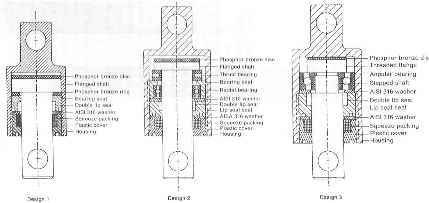
- From the Morphological Chart:
- Generated a large number of solutions
- Assembled “concept variants”
- How to evaluate these solutions?
What makes one “better” than another?
- Knowing how to choose between alternatives is an important design
activity!
- One can choose by some arbitrary manner, but it is best to use
a rational approach that can be clearly explained to managers and
clients.
- What makes a Decision Matrix a rational approach?
- Weighted numerical scores are assigned to various sub-objectives
- Individual scores are summed to give each overall solution choice a
numerical score
|
|
75
|
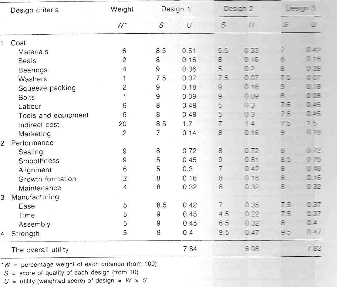
- List the design objectives
- Use the Objectives Tree
- The initial list might have been changed
- Rank order these from most to least important
- A rank order is a list from most important to least. Pair-wise
comparison may help in ordering them (see lecture 3).
- Rank ordering is an example of and ordinal scale.
- Assign relative weighting to these objectives
|
|
76
|
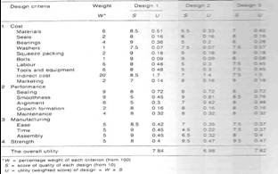
- Establish performance parameters (utility scores) for each of the
objectives
- It is necessary to convert the statement of objectives into parameters
that can be measured.
- The easiest way is to use five grades scale (0-4) with the following
ranking:
- Far above average – Excellent (4)
- Above average – Very good (3)
- Average - Good (2)
- Below average - Satisfactory (1)
- Far below average - Not satisfactory (0)
- Base the parameter estimation on common sense, your existing knowledge,
calculations, research on web, catalogs, etc.
- REMEMBER: If your estimates are bad, then the resulting decision matrix
results will be bad
- Calculate and compare the relative utility values of the alternative
designs
- In general, higher values mean better concept variant
|
|
77
|
|
|
78
|
- To encourage communication between team members and sub teams
- To review progress, time keeping and project standards
- To set targets for further tasks
- To meet experts when necessary
- To meet people from project management and planning, manufacturing or
administration
|
|
79
|
- Development of virtual reality learning environment for Design teams at
City University
- Project plan and specification
- Equipment: computers, cameras …
- Recording of all meetings and other phases of project
- Final report, oral presentations, panels …
|
|
80
|
|

 Notes
Notes