|
|
|
|
|
|
|
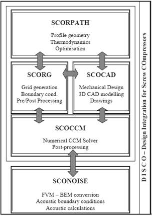
The interface is written in Visual basic suitable for any Windows based operating system. Other in-house components such as SCORPATH and SCORG are written in Fortran and are available for most operating systems including UNIX and LINUX. CAD systems are also available for all operating systems while CCM software typically runs on UNIX and LINUX machines but is in some cases available for Windows as well. The interface requires only shared input
parameters to describe the geometric and operating conditions of a screw
machine. It allows full control over each step of the design process,
providing that all changes in the final model are communicated back to the
previous design phases and vice versa. The emphasis is therefore on the
central parametric control and the reduction in number of data. |
|
|
This relaxes the computer resource requirements, as well as reducing the required time to conduct the full mechanical design of screw machines, when compared to traditional design processes. SCORPATH generates rotor profiles by the use of curves given
for one rotor being applied to the other or from a common rack using the
envelope gearing method. The result is given in the form of 2-D output
coordinates later used by the CAD system to generate the 3-D geometry.
Additionally, SCORPATH utilises the forces on the compressor rotors, derived
from thermodynamic calculations, for the further mechanical design of the
machine. The results are stored as standard ASCII files. SCOCAD organises output data from SCORPATH into a standardised database, with unique structure for all screw machine designs available, to be implemented to an arbitrary CAD system. These data are provided as the coordinate points for rotors, ports and the manufacturing tool. Since these are automatically transferred to the CAD system, the 3D solid model can be built in a short time. Additionally, parametric organisation of the data interchange through the external data base enables the design to be easily modified not only from the CAD system itself but also from both the external database and the SCOCAD environment. Being incorporated in DISCO, SCOCAD then enables the design changes to be introduced to other applications also integrated in DISCO. In addition, it permits the calculation and/or the selection of the machine elements from a database independent of the CAD system. The 3-D solid model obtained from the CAD system serves as a basis for rapid prototyping, while drawings are automatically provided to support more conventional manufacturing methods. SCORG prepares a numerical mesh of the domains in the vicinity of the rotors for 3-D flow and structure analysis. This is done by integrating the data of rotor and rack profiles from the SCORPATH input. At the same time, SCOCCM uses the integration of CAD and CCM software to generate polyhedral numerical meshes of the stationary parts of the numerical mesh. It then integrates the compressor geometry and working parameters generated by the SCORG and CAD systems with the commercial CCM, software. The computational grid of the screw compressor rotors generated by SCORG and the numerical grid of other parts of the compressor, including the suction or the discharge chambers, which may be generated from either the SCORG or the CAD system, are imported into the CCM software through the pre-processor script file. That file also contains working parameters, information of the differencing scheme and other required solver information. Finally, the results obtained from the CCM calculations are evaluated so that the design of the machine can be reviewed and changed if required.
SCORPATH
SHAPE \* MERGEFORMAT Mathematical modelling and computer simulation are now employed extensively for the analysis and design optimisation of screw compressors and by their use, new screw rotor profiles have been developed to improve machine performance. Descriptions of this are given is given in publications available on the City Compressor Centre web site, which contain details of various approaches to one dimensional flow analysis of screw compressors and how this is used to estimate performance. The software developed and used by the authors for the conceptual as well as the preliminary design of screw machines is called SCORPATH Screw Compressor Rotor Profiling and Thermodynamics. It calculates and optimises compressor performance for a specified duty. To start the procedure of rotor profiling, the profile point coordinates in the transverse plane of one rotor, and their first derivatives, must be known. The full rotor and compressor parameters, in the form of rotor throughput, rotor displacement, size of leakage flow area, as well as suction and discharge port coordinates are calculated from the rotor transverse plane coordinates and rotor length and lead. They are later used as input parameters for the calculation of the thermodynamic and fluid flow processes within the screw compressor as well as for further design tasks, such as the generation of detailed drawings. The algorithm of the thermodynamic and flow processes used is based on a mathematical model comprising a set of equations which describe the physics of all the processes within the screw compressor. Press here for full details. Depending on their field of application and whether they operate in the dry or oil-flooded mode, the requirements for optimum design of screw compressor rotors and other elements differ for each application and working fluid being compressed. Multivariable optimisation therefore should be employed as an important element in the design procedure, while optimisation targets must be set according to the design requirement. Thus, if high efficiency is required, the specific power or adiabatic and volumetric efficiencies will be targets. However, if the compressor capacity is to be maximized to keep the cost to a minimum, then compressor flow will be the optimisation target. A box constrained simplex method was used here to find the local minima.
SCORG
SHAPE \* MERGEFORMAT SCORG (Screw COmpressor Rotor Geometry Grid generator), is the grid generator and integration software which enables a grid, generated by the program, to be directly transferred to a commercial CFD code through its own pre-processor. This method took advantage of the work done by Peric and Demirdzic, who showed that by the use of moving frames on structured and unstructured grids, a common numerical method could be used for the simultaneous solution of fluid flow and structural analysis. A number of commercial numerical solvers are currently available, of which SCORG employs Star CDs COMET for screw machine calculations. That code offers the possibility to calculate both the fluid flow and its effects on the solid structure simultaneously by the application of CCM. The interface employs a novel procedure to discretise rotor profiles and to adapt boundary points for each particular application. An analytical transfinite interpolation method with adaptive meshing is used to obtain a fully structured 3-D numerical mesh, which is directly transferable to a CFD code. This is required to overcome problems associated with moving, stretching and sliding rotor domains and to allow robust calculations in domains with significantly different ranges of geometry features. SCORG prepares a numerical mesh of the domains in the vicinity of the rotors for 3-D flow and structure analysis. This is done by integrating the data of rotor and rack profiles from the SCORPATH input. At the same time, SCOCCM uses the integration of CAD and CCM software to generate polyhedral numerical meshes of the stationary parts of the numerical mesh. It then integrates the compressor geometry and working parameters generated by the SCORG and CAD systems with the commercial CCM, software. The computational grid of the screw compressor rotors generated by SCORG and the numerical grid of other parts of the compressor, including the suction or the discharge chambers, which may be generated from either the SCORG or the CAD system, are imported into the CCM software through the pre-processor script file. That file also contains working parameters, information of the differencing scheme and other required solver information. Finally, the results obtained from the CCM calculations are evaluated so that the design of the machine can be reviewed and changed if required.
SCOCAD
SHAPE \* MERGEFORMAT Preliminary mechanical design may be performed in either interactive or generative mode by use of a CAD system on the basis of the data calculated from SCORPATH. Traditional CAD systems are limited to the representation of geometric data and other types of information relating to geometry such as constraints, parametric information, features, etc. However, implementation of function, behaviour and structure of a specific machine such as compressor is not accounted for in them. The engineering design community has been developing new classes of tools to support knowledge-based design, product data management (PDM) and concurrent engineering. When contrasted with traditional CAD tools, these new systems are improved but still mainly database related. Also, although these systems can represent some kinds of non-geometric information such as design process details, bills of materials, etc, the representation of the design object itself is still generally limited to geometric considerations. Evidence of this may be found by reviewing the projects described on the IAI web page. Due to these limitations, further interoperability is required to enable full interaction between any CAD system and performance calculation programs such as SCORPATH. Any detailed mechanical design, that is to be performed later, may be conducted with a different CAD system to the one used in the previous design phase. As a result, manufacturing drawings can be produced and a numerical basis for manufacturing process generated based on information exchange between them through standard IGES, STEP or likewise integration. Available standards can be reviewed on either the IAI or the ISO web pages. Part of the CAD system should be related to the selection and/or calculation of mechanical properties of compressor elements. Some of these are: bearing selection based on life theory, selection of bolts and screws, checking of shaft deflections and strength, selection of keys and key-ways, dowels etc. The majority of CAD software allow such calculation through integrated CAE components. However, these generally require substantial action by the user in order to set up and relate loads and restraints calculated outside the CAD system with geometry created within the CAD system. SCOCAD therefore organises output data from SCORPATH into a standardised database, with unique structure for all screw machine designs available, to be implemented to an arbitrary CAD system. These data are provided as the coordinate points for rotors, ports and the manufacturing tool. Since these are automatically transferred to the CAD system, the 3D solid model can be built in a short time. Additionally, parametric organisation of the data interchange through the external data base enables the design to be easily modified not only from the CAD system itself but also from both the external database and the SCOCAD environment. Being incorporated in DISCO, SCOCAD then enables the design changes to be introduced to other applications also integrated in DISCO. In addition, it permits the calculation and/or the selection of the machine elements from a database independent of the CAD system. The 3-D solid model obtained from the CAD system serves as a basis for rapid prototyping, while drawings are automatically provided to support more conventional manufacturing methods.
SCOCCM
SHAPE \* MERGEFORMAT In the final stage of the design process, screw compressor performance may be estimated more precisely by use of Three-dimensional Computational Fluid Dynamics (CFD) or Computational Continuum Mechanics (CCM). Please search Compressor Centre Bibliography. The aim of 3-D numerical simulation is not to reconfirm 1-D calculation of thermodynamics but rather to serve as an optimisation tool for the suction and discharge ports as well as to provide the flow information needed for flow-structure analysis. The same numerical grid is simultaneously used for estimation of distortions of the compressor elements and its influence to the flow parameters. A number of commercial CFD software packages are currently available which may be able to cope with the complexity of flow through screw machines and which may be integrated with CAD. However, the authors most commonly employ COMET of Star CD for screw machine calculations, firstly, because that code enables both fluid flow and its interaction with the solid structure to be calculated simultaneously by use of the Computational Continuum Mechanics (CCM) principle already incorporated in the code. Secondly, because the code, as a CAE package, is already integrated in some CAD systems. This made the development of the integration software easier. Thirdly, it uses a modern polyhedral topology of computational control volumes to map the geometry. Polyhedral cells allow both easier grid generation and more accurate solution in a mesh with a lower number of cells. This improves the computational speed. However developed new codes are, there are still limitations of their use in some specific application. For the analysis of screw machines, a moving, stretching and sliding mesh has to be produced to map the working chamber of a machine. Todays grid generators are still not capable of coping with these demands.
|
|