Replacing a Surface
| The Replace command lets
you replace sketches, faces, planes and surfaces by other appropriate
elements.
This task shows you how to replace a surface used for creating geometry with another surface. |
|||
| The operating mode described here is valid for replacing the geometrical elements used in the definition of any Part Design features. | |||
| Open the Replace1.CATPart document. | |||
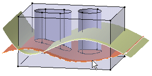
| 1. | Select Extrude.1, that is the red surface used for trimming both the pocket and the hole. | ||
 |
|||
| 2. | Right-click to display the
contextual menu and select the Replace...
command.
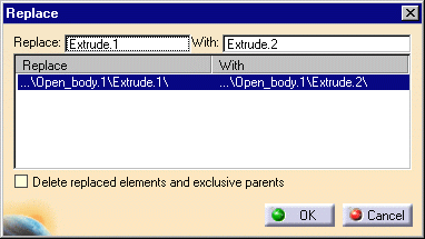
The Replace dialog box is displayed, indicating the name of the surface to be replaced. |
||
| 3. | Select Extrusion 2 as the replacing surface. Extrusion 2 now appears in the With field of the dialog box. | ||
 |
|||
| 4. | Check the Delete option to delete Extrusion1. | ||
| 5. | Click OK to confirm the operation. | ||
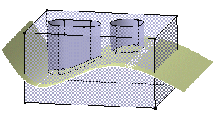
| The pocket and the hole are now trimmed by Extrusion 2. Extrusion 1 has been deleted. |  |
||
|
|
|||