Weld Planner

This task  shows you how to set welding specifications on components. These specifications will be used later to weld these components.
Open the WeldPlanner.CATProduct document.
1.   Click the Front View as shown to define the plane in which you will display the specification.

The view becomes red meaning that it is active. In the specification tree, it is underlined.

If the active view is not valid, a message appears informing you that you cannot use the active view. Therefore, the application displays the annotation in an annotation plane normal to the previously selected element.
2.  Click the Weld Planner icon.
3.  Select the edge between Green Part and Blue Part.

The Weld Planner and the Welding Creation dialog boxes appear. The Weld Planner dialog box displays the name of the selected geometric element, the name of the corresponding component and the status of the component. 

3.

Enter "Welding 2"  in the Name entry field to rename "Weld Planner.2".

This new name appears in the specification tree under Weld Planners section.

4.  Enter your specifications in the Welding Creation dialog box. In the first entry field to the left, enter 70 as the weld length. 
5. For example, set the angle symbol. The symbols available are:
6.  Choose among the three weld types available to set your weld type:
7. Enter 2.5 as the weld size. 
8. Enter Weld 2 in the Reference entry field. This field is reserved for your own specifications or codes.

You can also import a file by clicking the Import file button. The contents of this file is then displayed in the geometry.

Note also that you can click:
the field-weld symbol (flag symbol): reserved for welds not made at the location of the initial part construction.
the weld-all-around symbol (circle circle): reserved for welds made all around the contour of the part
the "up" option: a display option. You can display the symbols and values above or below the welding symbol. It is a quick way of transferring the data from the first row to the row below and vice versa.

9. Click OK to confirm.

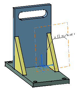
The annotation is created in the geometry.

  10. Drag and drop the annotation to move it. 

You can obtain this result:

The contextual command "Add Leader" is available on specifications: it adds a leader to the selected specification (Right-click the specification to which you want to add a leader, select the Add Leader contextual command and click where you want to begin the leader).
Contextual commands are also available on the yellow manipulator at the extremity of the arrow end:
Add a Breakpoint: adds a breakpoint on the leader line 
Remove a Breakpoint: removes a breakpoint on the leader line 
Remove Leader: removes a leader line
Symbol shape: edits the shape of the manipulator pointed at by the arrow


At any time, you can modify the welding symbol. For this, double-click the welding symbol to be modified and enter the modifications in the displayed dialog box.
 

Up Next