Modifying a Callout Graphism
| This task will show you how to modify the graphical attributes of one or more callout used when generating auxiliary, section or detail views. | |||||||||||||||||||||||||||||||||||||||
| Before You Begin, make sure you customized the following settings:
Grid: |
|||||||||||||||||||||||||||||||||||||||
| Open the GenDrafting_part_Callout.CATDrawing document. | |||||||||||||||||||||||||||||||||||||||
| 1. Multi-select
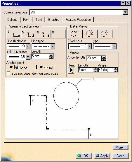
the callout to be modified. In this example, we select both a section view callout and a detail callout. 2. Right-click these callout and select the Properties option from the contextual menu. 3. Select
the Callout tab. |
|||||||||||||||||||||||||||||||||||||||
|
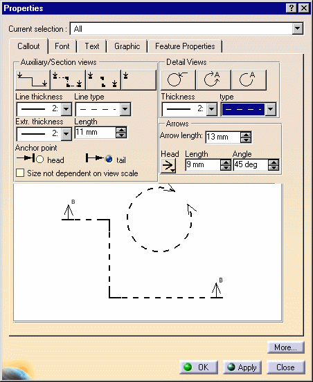
The preview displays both selected callout with attributes corresponding
to the generated views.
|
|||||||||||||||||||||||||||||||||||||||
The options you select in the Graphic
Properties toolbar also influence the graphical attributes you apply to
the selected callout (line color, line type, line weight, Copy Object Format icon,
Pattern Chooser option).
|
|||||||||||||||||||||||||||||||||||||||
|
|||||||||||||||||||||||||||||||||||||||
|
|||||||||||||||||||||||||||||||||||||||
You can choose the callout elements size not to be dependant on the view scale. For this:
or
4. Modify the callout graphical attributes as shown above. 5. Press OK.
|
|||||||||||||||||||||||||||||||||||||||
|
|||||||||||||||||||||||||||||||||||||||


