Computing Objects Sets
| A finite element computation is a
succession of data manipulation processes in which input data resulting
from a previous process (or directly input by the user) is converted into
output data ready to be used by a subsequent process. Such ready-to-use
data is stored in program objects sets such as those appearing
in the analysis features tree under Analysis Cases (Restraints, Loads,
Masses, Solutions) objects sets. When data contained in such an objects set is ready for use in the subsequent finite element computation process, the object has been computed and can be analyzed. Thus, Computing an objects set consists in generating finite elements results for all objects and objects sets necessary to analyze the specified objects set. The computation of an objects set requires two distinct actions:
As a result of such action, the program translates the user-defined specifications into solver-interpretable commands applied on mesh entities, and you can visualize on the mesh the result of this translation. This analysis capability, used especially for displaying program feedback on applied Restraints, Loads or Masses objects in the case of large size models (when you do not wish the entire computation to be performed), is available with a right (key 3) click on:
A prerequisite to these actions is the existence of a Mesh.
|
|||||||||||||
| Avoid having CATAnalysis documents automatically saved. For
this, go to Tools->Options->General (menu bar) and
de-activate the Automatic save every xx minutes option.
Otherwise, on some models, each computation will be followed by a Save,
thus making temporary data become persistent data.
This task shows how to compute a Mesh. Computing a Mesh will enable the analysis of any object of Restraints, Loads and Masses type, without requiring the computation of a Solution.
|
|||||||||||||
|
You can use the sample00.CATAnalysis document from the samples directory for this task: Finite Element Model containing a Static Analysis Case and computed corresponding Static Solution.
|
|||||||||||||
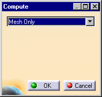
| 1. Click the Compute icon The Compute dialog box is displayed. The combo box allows you to choose between several options for the set of objects to update:
The Preview switch allows you to obtain an estimate of the time and memory required to perform the computation. 2. Select Mesh Only.
3. Click
OK in the Compute dialog box. A valid Mesh object also appears under the Nodes and Elements objects set.
|
|||||||||||||
|
Any object in the Finite Element Model can now be analyzed (visualized on the Mesh). By extension, all objects belonging to any objects set in the Finite Element Model can also be analyzed (visualized in various Generated Images or analyzed in a Report). For mode details on object Visualization on Mesh and on objects set Report and Image Generation, see the creation of objects of Restraints, Loads and Masses types. You can change the definition parameters of an object either by replacing it by a new one (delete followed by create) or by modifying it (edit the definition parameters).To edit the definition parameters of an object, activate it in the analysis features tree and double-click the object (or right-click, then click .Object -> Definition ) to re-display the object definition dialog box.
|
|||||||||||||
|
|


