Creating Sensors (Static Analysis Case)
| Static Analysis Case This task shows you how to access knowledge output values by adding them into a set called Sensors.
|
|||||||||||||||||||||
| You can use the Sample08.CATAnalysis
document from the samples directory for this
task.
Before You Begin:
|
|||||||||||||||||||||
Sensors Set |
|||||||||||||||||||||
|
|
1. Right-click on the Sensors feature that appears by default in the specification tree.
Note that, in the specification tree, one sensor set appears per analysis case and that the Energy feature is also displayed, by default. 2. Select the Create Sensor
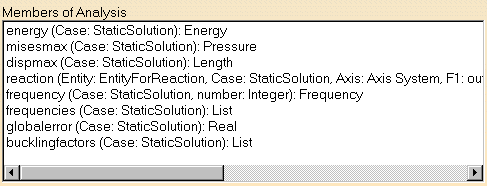
option that is available in the contextual menu. The following values are available (depending on the type of the case, different values can be accessed and added to the Sensors set):
3. Insert the sensors values available for the current static case into the specification tree, one after the other. This
list of the values that can be accessed and
added corresponds to the functions available in Knowledgeware.
These functions are available without having to enter the Formula
When inserting the reaction value, the Reaction Sensor dialog box appears: 4. If needed, select the desired Available
Entities (previously created on the CATAnalysis document) from the
Reaction Sensor dialog box.
The following Entities are available:
The following Axis Types are available:
The reference axis is the axis in which the reaction tensor will be computed and displayed in the 3D view. The specification tree will result as shown here:
|
||||||||||||||||||||
Output Information
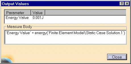
5. If needed, double-click on the desired values in the specification tree to have the output information available via the Output Values dialog box. If the sensor is not up-to-date, you will get a warning message that let you know that to have the current solution be computed and the sensor be updated, you must use the Compute All command. The Output Values dialog box displays the body of the measure which
corresponds, in Knowledgeware, to the signature of the
function.
The Parameter default name can be edited. For this, double-click on the parameter value, modify the name and click OK in the Output Values dialog box to have the new name actually taken into account. Energy
Maximum Von Mises
Maximum Displacement
Reaction (Reaction Tensor dialog box) The axis corresponds to the axis in which the reaction tensor is computed and displayed. Three tabs are available:
Global Error 6. Click Close in the Output Values dialog box once you are satisfied with the information.
|
|||||||||||||||||||||
|
|


