Rib
| Open profile | Closed profile | Pulling direction | |
| Open center curve |
|
|
|
| Closed planar center curve | |||
| Closed 3D center curve |
|
Moreover, the following rules should be kept in mind:
|
|||||||||||||
|
Open the Rib1.CATPart document. |
|||||||||||||
| 1. | Click the Rib icon The Rib Definition dialog box is displayed. |
||||||||||||
|
|
|||||||||||||
|
2. |
Select the profile you wish to sweep, i.e. Sketch.2 . Your profile has been designed in a plane normal to the plane used to define the center curve. It is a closed profile. |
 |
|||||||||||
About Profiles
|
|||||||||||||
|
|
|
||||||||||||
|
Profiles |
Result |
||||||||||||
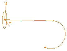
| 3. | Select the center curve, i.e.
Sketch.1. The center curve is open. To create a rib you can use open profiles and closed center curves too. 3D Center curves must not be discontinuous in tangency. |
||||||||||||
| You can also use planar wireframe geometry as your profile or center curve. | |||||||||||||
| Clicking the icon |
|||||||||||||
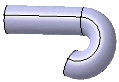
| The application now previews the rib to be created. | |||||||||||||
|
|
|||||||||||||
You can control its position by choosing one of the following
options:
|
|||||||||||||
| 4. | To go on with our scenario, let's maintain the Keep angle option. Remember, the angle value is 90 degrees. | ||||||||||||
| 5. | Click OK. The rib is created. The specification tree mentions this creation. |
||||||||||||
 |
|||||||||||||
| The Merge ends option is to be used in specific cases. It create materials between the ends of the rib and existing material provided that existing material trims both ends. | |||||||||||||
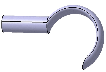
| 6. | Delete this rib to create another
one by using the Pulling direction option. After setting this option,
select plane xy to define z axis as the pulling direction. The plane used
to define the profile will remain normal to plane xy.
The preview looks like this: |
||||||||||||
|
|
|||||||||||||
| And the rib like this: | |||||||||||||
|
|
|||||||||||||
| 7. | Delete this rib to create another
rib by using the Reference surface option.
First, display the loft in the Show space, then set the Reference surface option and select the loft as the reference surface. The angle value between h axis and the surface equals 0. It remains constant. The preview looks like this: |
||||||||||||
|
|
|||||||||||||
| And the rib like this: | |||||||||||||
|
|
|||||||||||||
| 8. | Check the Thick Profile option to add thickness to both sides of Sketch.2. New options are then available: |  |
|||||||||||
| 9. | Enter 2mm as Thickness1's value, and
5mm as Thickness2's value, then preview the result.
Material is added to each side of the profile. |
||||||||||||
|
|
|||||||||||||
| Checking the "Merge Ends" option trims the rib to exiting material. | |||||||||||||
| 10. | To add material equally to both
sides of the profile, check "Neutral fiber" and preview the
result.
The thickness you defined for Thickness1 (2mm) is now evenly distributed: a thickness of 1mm has been added to each side of the profile. |
 |
|||||||||||
| 11. |
Click OK to create the rib. The rib looks like this: |
||||||||||||
|
|
|||||||||||||
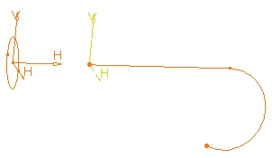
A Few Words about the Keep Angle Option
| The position of the profile in relation to the center curve determines the shape of the resulting rib. When sweeping the profile, the application keeps the initial position of the profile in relation to the nearest point of the center curve. The application computes the rib from the position of the profile. | |
| In the example below, the application computes the intersection point between the plane of the profile and the center curve, then sweeps the profile from this position. | |
 |
 |
|
|
 |
|
|