'Up to Next' Pads
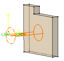
| This task shows you how to create a pad using the 'Up to Next' option. This creation mode lets the application detect the existing material to be used for trimming the pad length. | |||||
| Open the Pad2.CATPart document. | |||||
| 1. | Select the profile to be extruded, that is the circle. | ||||
| 2. | Click the Pad icon The Pad Definition dialog box appears and the application previews a pad with a default dimension value. |
||||
| 3. | Click the arrow in the geometry area to reverse the extrusion direction (or click the Reverse Direction button). | ||||
|
|
|||||
| 4. |
In the Type field, set the option to 'Up to next'. |
 |
|||
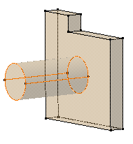
This option assumes an existing face can be used to limit the pad. The application previews the pad to be created. The already existing body is going to limit the extrusion. |
 |
||||
| Optionally, click Preview to see the result. | |||||
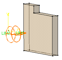
| 5. | Click OK. The pad is created. The specification tree indicates this creation. |
 |
|||
|
By default, the application extrudes normal to the plane used to create the profile. To learn how to change the direction, refer to Pad not Normal to Sketch Plane . | ||||
|
|
|||||
