COMPUTATIONAL FLUID DYNAMICS AND STRESS ANALYSIS IN SCREW COMPRESSOR DESIGN
City University Compressor Centre is a world leader in application of the Computational Fluid Dynamics (CFD) in screw compressor calculations.Computational Fluid Mechanics analysis may be used to estimate velocity, pressure, temperature and concentration fields, as well as stress and deformation within within a screw compressor accurately. A rack-generation procedure produces rotor profiles and an analytical transfinite interpolation method obtains a 3-D numerical mesh. An adaptive meshing, orthogonalization and smoothing are employed to generate a numerical grid which takes advantage of the innovative techniques used in recent finite volume numerical method solvers. This was used to develop an independent stand-alone CAD-CFD interface program to generate a numerical grid of the screw compressor. These were required to overcome problems associated with i) rotor domains which stretch and slide relative to each other and along the housing ii) robust calculations in domains with significantly different geometry ranges, iii) a grid moving technique with a constant number of vertices.
Modifications are also implemented to the CFD procedure improved solutions in complex domains with strong pressure gradients. Typical results arising from its use when linked to Comet (www.iccm.de), a commercial CFD solver, are shown for an oil-flooded screw compressor. Examples of the screw compressor has been given to demonstrate the scope of the method for accurate calculation of processes within these machines.
More information on Screw Compressor CFD and FSI can be found here. For additional information, please refer to Bibliography.The computational mesh of the male rotor is given in the first animation, the pressure and velocity fields within the compressor are presented and in other animations. Please alow some time for animations to load.
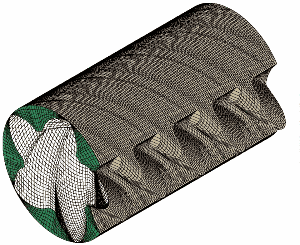
Numerical grid of a screw compressor working chamber - fluid domain
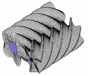
Numerical grid of screw compressor rotors - solid domain
Some changes within the solver were made to increase the speed of calculation. These include a novel method maintain constant pressures at the inlet and outlet ports and consideration of two phase flow resulting from oil injection in the working chamber.
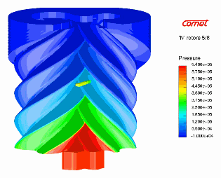
Pressure field on the rotors, solid model
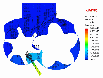
Pressure field and velocity distribution, cross-section
The pre-processor code and calculating method have been tested on a commercial CFD solver to obtain flow simulations and integral parameter calculations.
The results of calculations on an oil injected screw compressor are compared with experimental results. Good agreement was obtained between them.
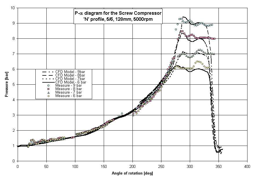
p-angle diagram, comparison with the experimental results
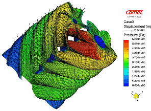
Rotor deformation due to pressure forces
![]()