| Screw Machine Basics | |
| Introduction
Screw compressors are becoming more popular machines, comprising a majority
of the world production of industrial compressors. A screw machine is a
positive displacement rotary machine consisting of a meshing pair of helical
lobed rotors, contained in a casing, which together form a working chamber
whose volume depends only on the angle of rotation. Its configuration is
complex and the relative motion of its moving components involves both
rotation and sliding. Its performance is highly affected by leakages,
which are a direct function of clearance gaps both between the rotors and
between the rotors and the housing. As a result of advances both in their
profiling and in their techniques of manufacture, rotors of even the most
complex shape, can now be manufactured to tolerances of as little as +/-
5 mm. Thus, clearance gaps in modern machines have become much smaller
than they were fifteen years ago and this has enabled screw compressors
to be manufactured as compact and reliable machines of very high efficiency.
More information
on on crew compressors. Consequently, the screw machine is now the
most widely used type of industrial compressor. Screw compressors may be
broadly classified under two categories; namely oil injected and oil free.
Oil Injected Compressors In the case of oil injected compressors, the gas to be compressed, whether air or refrigerant, enters the compressor together with a substantial percentage by mass, though a small percentage by volume, of lubricating oil or cooling liquid. By this means, one rotor may drive the other without the need for synchronising gears to prevent contact, the gas temperature rise is reduced, thereby permitting high pressure ratios, and leakage losses are minimized. The disadvantages of oil injection are that the compressor unit must include an oil separator, to remove the oil from the gas after compression, and rotational speeds must be kept low because of high associated friction losses. The development of oil injected compressors has now reached an advanced stage. The relatively large mass of oil entrained in the compressed gas implies that the temperature rise of the gas during compression is only of he order of 50oC, even at relatively high discharge pressures. Thus there is little thermal distortion and rotor clearances can be maintained at 30 micrometers or less. By this means compressor adiabatic efficiencies of over 90% have been achieved even in machines with power inputs of less than 50 kW.
Fig 1. Oil Flooded Compressor
Oil free compressors Oil free compressors operate with dry gas only and accordingly rotate
with much higher tip speeds, thus making them more compact. However, relatively
expensive timing gear is required to prevent contact between the rotors
and the lack of oil means that gas temperatures rise steeply within the
machine. Particularly for air, where the isentropic index of compression
is high, even moderate pressure increases of the order of 3:1 lead to temperature
increases of over 180oC. Because the gas flow is not axisymmetric, this
leads to distortion of the casing. Accordingly, clearances have to be relatively
large to avoid contact and their magnitude is determined mainly from empirical
data. To minimise the need for large clearances in oil free machines,
their pressure ratios per stage are kept relatively small but in general,
oil free compressors are less efficient than their oil injected equivalent.
Also seals are required between the rotors and the bearings to prevent
oil leakage into the bearing housings and, in general, an oil free screw
compressor may cost four or more times as much as an oil injected compressor
of similar rotor dimensions. However, it should be noted that an oil free
compressor passes roughly twice the volume of gas and requires no oil separator.
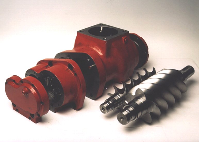
Screw compressor rotors Screw compressor adiabatic and volumetric efficiencies are greatly dependent
on both the profile and number of the lobes in each rotor. For high efficiency,
the requirements are for a large flow cross sectional area, short sealing
lines between the rotors in the axial direction and a small space between
the cusp of the casing and the rotor tips, which is known as the blow-hole
area. The larger the cross sectional area, the higher the flow rate
for the same rotor sizes and speeds. Shorter sealing lines and a smaller
blow-hole reduce leakages. Higher flow and smaller leakage rates both increase
the volumetric efficiency, which is the rate of flow delivered as a fraction
of the sum of the flow plus leakages. This in turn increases the adiabatic
efficiency because less power is wasted in the compression of gas which
is recirculated internally. Reduced leakage also leads to less noise generation
by the leakage flow. More information.
Fig. 2 Screw Compressor Rotors
Screw compressor design The development of oil injected compressors has now reached an advanced stage due to their relative simplicity. Modern anufacturing techniques make it possible to make rotors with manufacturing tolerances of 5 mm on a regular production basis while the relatively large mass of oil entrained in the compressed gas implies that the temperature rise of the gas during compression is only of the order of 50oC, even at relatively high discharge pressures. Thus there is little thermal distortion and rotor clearances can be maintained at 30 mm or less. By this means compressor adiabatic efficiencies of over 90% have been achieved even in machines with power inputs of less than 50 kW. Reasonably accurate performance estimates are possible with the assumptions of one dimensional flow of the air and that, due to centrifugal effects, the oil passes through the machine almost exclusively in contact with the casing bore surfaces. In the case of oil free compressors, especially for air, where the isentropic
index of compression is high, even moderate pressure increases of the order
of 3:1 lead to temperature increases of over 180oC. This, in turn leads
to the need for large rotor clearances to avoid contact due to distortion.
The need for these clearances, which are determined mainly from empirical
data, implies that oil free machines are generally less efficient than
their oil injected equivalent. It follows that if the thermal distortion
of the rotors and casing could be calculated with sufficient accuracy,
their design could be modified to minimize clearances under operating conditions.
Increases in adiabatic efficiency of the order of 10 percentage points
or more would then, therefore, be possible.
|