Step-by-Step Procedure
Controlling the Bearing Design with a Design Table
|

|
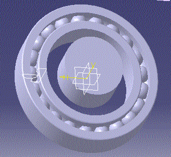
A design table is created from a pre-existing file. The data set
contained in this pre-existing file is quite similar to the data set which identifies a
bearing in a catalogue. The design table which is created defines a number of configurations.
Applying a new configuration results in a bearing modification. |
 |
-
Open the KwrBallBearing1.CATPart
document.
-
Click the  Design Table icon in the standard toolbar.
-
Check the Create a design table from a pre-existing file
option. Click OK.
-
Select the KwrBearingDesignTable.xls
file and associate automatically the design table columns and the document
parameters (i.e. click YES in the "Automatic Associations?" dialog box).
-
In the Design table dialog box, select the configuration 3
and click Apply.
Your ball bearing has changed. It is now an bronze bearing with 21 balls. You can tell
the difference when you look at the geometry area. The bearing width is also modified.
Click OK to exit the Design Table dialog box. Keep your document open and
proceed to the next task.
|

Creating a Check
|
|
A combined check using the => syntax is created. This check is intended to
display a message whenever the check is not satisfied. |
|
-
Access the Knowledge Advisor workbench
-
Click the  icon then click OK in the first Check Editor dialog box. The check
editor is displayed.
icon then click OK in the first Check Editor dialog box. The check
editor is displayed.
-
In the Check Editor, select the Warning type and enter the
string "BallNumber is too small" in the message field.
Then enter the
D3 >= 6mm => BallNumber > 6
relation in the edition box.
-
Click OK to create your check and exit the editor. At this stage, no
particular message is displayed. The check is added to the specification tree with a
green icon. For the configuration 3 of the design table, this is the status of the check
relations:
| OK => OK |
 |
In the specification tree, double-click the design table and select the
configuration 1. Click OK. The message "BallNumber is too small" is displayed.
For the configuration 1 of the design table, this is the status of the check relations:
| OK => KO |
 |
Keep your document open and proceed to the next task
|
Creating a Multiple Value Parameter
|
|
A multiple value parameter is created. Depending on this parameter value, a
rule which is created in the next task will display either a message or launch a macro. |
|
-
Click the  icon.
icon.
-
In the Formulas dialog box, select
String in the New
Parameter of type list. Select Multiple
values in the with list,
then
click 'New Parameter of type'.
-
In the Value List of String dialog box, enter one-by-one the
step1, step2 and step3 values. Click OK.
-
In Edit name or value of the current
parameter, replace the
String.1 string with Status, then click OK. The Status parameter is added to the
specification tree.
|
Creating a Rule
|
|
This task creates a rule which displays a message prompting you to import a file or
launches a macro. |
|
-
In the specification tree, double-click the design table feature and
select the configuration 3 in the table which is displayed. You are back to 21 ball
bearing.
-
Access the Knowledge Advisor workbench
-
Click the  icon.
icon.
-
Enter the Rule.2 string in the Name field of the first
dialog box. Click OK.
-
Copy/Paste the code below into the rule edition box (modify the macro
path): if Status == "step2"
Message("Import the KwrBallBearingImport text file")
else if Status == "step3"
LaunchMacroFromFile("e:/tmp/KwrBearing.CATScript")
Click OK to add the rule to the document and execute it.
Click the
icon. In the "Formulas" dialog box, select the Status parameter and replace
its step1 value with step2. Click OK. A message asks you to import the KwrBallBearingImport
text file.
Click Import and select the KwrBallBearingImport.txt
file. Three parameters are then added to the document. Click OK in the dialog box
displaying the parameters and formulas to be imported.
Select the Status parameter and replace the step2 value with step3.
Click OK. The KwrBearing.CATScript is
executed and a circular pad is created.
|
|