Positioning Planes with respect to a Geometrical Target
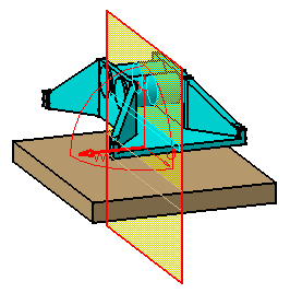
| You can position section planes with respect to a geometrical target (a face, edge, reference plane or cylinder axis). This task illustrates how to position a section plane on a geometrical target. | |||
| Open the AssemblyConstraint02.CATProduct document. | |||
| 1. | Click the Sectioning
A Preview window, showing the generated section, also appears. The generated section is automatically updated to reflect changes made to the section plane. |
||
|
|
|||
| 2. | Click
the Geometrical Target |
||
| 3. | Point
to the target of interest:
A rectangle and vector representing the plane and the normal vector of the plane appear in the geometry area to assist you position the section plane. It moves as you move the cursor. |
 |
|
| 4. | When satisfied, click to position the section plane on the target. | ||
|
|
|||
| Notes: | |||
|
|
|||
|
|||
| 5. | (Optional)
Click the Reset Position |
||
|
|
|||
| 6. | Click OK in the Sectioning Definition dialog box when done. | ||
|
|
|||


