Using the Section Viewer
| You can view the generated section in a separate viewer. This task illustrates how to make the most of section viewer capabilities. | |||
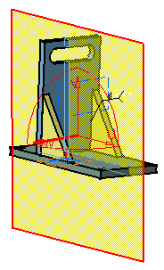
| Open the WeldPlanner.CATProduct document. | |||
| 1. | Click the Sectioning
A Preview window, showing the generated section, also appears. The generated section is automatically updated to reflect changes made to the section plane. |
||
|
|
|||
| 2. | Click
the Results
Window The results window is automatically tiled vertically alongside the document window. It displays a front view of the section and is by default, locked in a 2D view. |
||
|
|
|||
| 3. | Right-click
in the results window and select the 2D
Lock |
||
| 4. | Orient
the section.
Flip and Rotate commands are to be found in the contextual menu. Right-click in the results window and: |
 |
|
| 5. | Select
the Flip Vertical |
||
|
|
|||
| 6. | Select
the Rotate Right |
||
|
|
|||
Working with the 2D Grid |
|||
| 7. | Select
the Grid |
||
|
|
|||
| By default, grid dimensions are those of the bounding sphere. Simply re-dimension the section plane to modify grid size. | |||
| 8. | You can edit the grid step, style and mode using the Edit Grid icon.
Select
the Edit Grid The Edit Grid dialog box appears: |
 |
|
|
|
In the above example, the grid mode is absolute and the style is set to lines. The grid step is set to the default value of 100. Units are current units set using Tools-> Options (Units tab under General-> Parameters). | ||
| 9. | Set the grid step to 25 x 25. | ||
| 10. | Click
the Relative mode radio button:
In the relative mode, the center of the grid is placed on the center of section plane. |
||
| 11. | Click the Crosses style radio button. | ||
|
|
|||
| Grid parameters are persistent: any changes to default parameters are kept and applied next time you open the viewer or re-edit the section. | |||
| 12. | Click the Automatic filtering checkbox to adjust the level of detail of grid display when you zoom in and out. | ||
| 13. | Right-click the grid then select Coordinates to display the coordinates at selected intersections of grid lines. | ||
|
|
|||
| The Clean All contextual command removes displayed grid coordinates. | |||
| 14. | Click OK in the Sectioning Definition dialog box when done. | ||
|
|
|||