Creating a Projection View
| This task will show you how to create
projection views on the sheet, relatively to the front view previously
generated.
Projection views are views conceived to be drawn or projected onto planes known as planes of projection. A transparent plane or pane of glass representing a plane of projection is located parallel to the front surfaces of the part. |
| Before You Begin, make sure you customized the following settings:
Grid: View names and scaling factors: 3D colors inheritance |
| Open the GenDrafting_front_view.CATDrawing document. | |
| 1. Click the Drawing window, and
double-click the Projection View icon
|
|
|
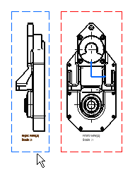
As you move the cursor, a previewed projection view in a green frame appears on the sheet. 2. Define the projection view position by positioning the cursor at the desired view location, for example the right view position. 3. Click inside the green frame to generate the view.
|
|
| Note that the left view above was created and therefore positioned according to the first projection method. Projection methods are described in Creating Views via the Wizard. | |
|
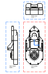
4. Define the bottom view position. 5. Click inside the sheet to generate the view.
|
|
|
|


