Creating an Area Fill
|
An area fill is a closed area on which you then apply graphical dress-up element called patterns (these can be hatching, dotting or coloring). You can create area fills on the following elements: | |||||||||||||||
In this task, you will learn how to create an area fill on a drawing containing a mix of sketched and generated elements. |
||||||||||||||||
| Open the GenDrafting_Area_Fill.CATDrawing document. This drawing is a generated one. | ||||||||||||||||
|
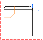
Define boundaries for your area fill by creating
lines so that your drawing looks like the figure shown here. In this example,
sketched elements (the ones you create) are selected (they are shown in
red), and generated elements are shown in black.
The boundaries for your area fill will therefore consist of both sketched and generated elements. |
 |
|||||||||||||||
| You do not need to activate the view
in which you are going to create an area fill.
|
||||||||||||||||
1. In the
Graphic Properties toolbar, click the down arrow besides the Pattern
2. In the Pattern dialog box, select a pattern for your area fill and click OK. 3. Click Insert -> Dress Up -> Area Fill. OR Click the Area Fill icon |
||||||||||||||||
| The Area Detection dialog box appears. |  |
|||||||||||||||
|
|
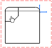
4. Click the Automatic option (the other option is described in the remarks section below) and then click inside the area for which you just defined boundaries, under the line which represents the fillet edge. |
 |
||||||||||||||
The software automatically detects the area to fill based on where you clicked and fills this area with the selected pattern. The Areas to Fill dialog box disappears. |
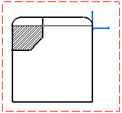 |
|||||||||||||||
A few remarksArea to Fill dialog boxThe two options available in the Area to Fill dialog box are described below. You can specify the area you want to fill before or after choosing the option in the Area to Fill dialog box. For each option, examples illustrate what kind of area fill you will get depending on where you click. Note where the cursor is located on the figures.
|
||||||||||||||||
If you click in this area: |
You get this area fill: |
|||||||||||||||
|
|
|
|||||||||||||||
|
||||||||||||||||
|
|
|||||||||||||||
If you select these elements: |
You get this area fill: |
|||||||||||||||
|
|
|
|||||||||||||||
|
|
Miscellaneous remarks about applying area fills
|
|||||||||||||||
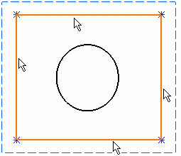
What you have before applying the pattern: |
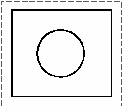
What you get if the pattern cannot be displayed: |
|||||||||||||||
|
||||||||||||||||


