Visualizing Deformations
| Deformed Mesh images are used to visualize the finite
element mesh in the deformed configuration of the system, as a
result of environmental action (loading). Deformed Mesh Image objects can belong to Static Case Solution objects
sets or to Frequency Case Solution objects sets.
|
|||||
| This task shows how to generate Deformed Mesh
images on parts.
|
|||||
You can use the sample23.CATAnalysis document from the samples directory for this task. Before You Begin:
|
|||||
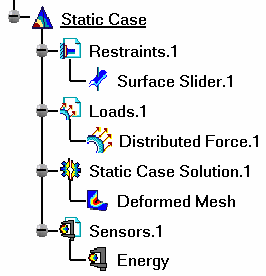
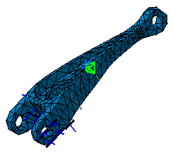
| 1. Click the Deformation icon The Deformed Mesh object appears in the specification tree under the active Static Case Solution objects set.
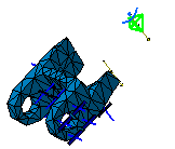
The Deformed Mesh on the part is visualized.
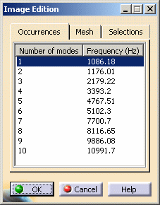
2. Double-click the Deformed Mesh
object in the specification tree to edit the image.
Under the Mesh tab, the Display on Deformed Mesh switch and the Shrink Coefficient let you modify the image characteristics.
These mesh entities are either all the elements included in the mesh part or the elements or nodes associated to the geometry supporting a specification. This is available for all types of specifications: Mesh specifications, Connections, Loads, Restraints and Masses. The mesh entity you select in the dialog box (whatever the type) corresponds to the visualized selection.
The image corresponding to the settings you defined is now visualized. You can use the right mouse click (key 3) on a Deformed Mesh Image feature in the specification tree and select the option called Activate/Deactivate to turn the corresponding image on or off.
|
|||||
| Products Available in Analysis Workbench
Report: this option generates a report in .html and .txt formats.
|
|||||
|
|||||
|
|||||
|
|


