Before You Begin
| Before you begin you should be familiar with the following basic
concepts:
|
|||||||||||||||||||
What Type of Analysis for What Type of Design?You will find here below three methodological cases for generating mesh, depending on the type of the geometry.
Analyzing in "Generative Part Structural Analysis"
Workbench (GPS)
After Meshing in "Advanced Meshing Tools workbench" (FMS)
|
| The selected FMS mesh part will be used for analysis. | |
| This mesh contains triangle and quadrangle shell elements. Those elements can only be linear (three nodes-four nodes). They have six degrees of freedom per node (three translations and three rotations) to take into account membrane and bending effects. | |
| The thickness of the part needs to be specified by double-clicking on Material Property in the specification tree. | |
| All the preprocessing specifications (Loads,
Restraints, Masses) will have to be applied to the geometries that
were selected
in FMS workbench (by clicking the Surface Mesh |
Analyzing in "Generative Part Structural Analysis" (GPS)
Workbench Surface Geometry Designed in "Generative Shape Design"
(GSD) Workbench


- First case
You first indicated in GSD which geometry you want to be analyzed by going into Tools -> External View commands from the menu bar.
The following will be generated: mesh parts and shell properties.
A 2D Octree mesh Part is automatically created when starting GPS.
This mesh part will generate triangle shell elements. Those elements can be linear (three nodes) or parabolic (six nodes). They have six degrees of freedom per node (three translations and three rotations) to take into account membrane and bending effects.
- Second case
You did not indicate in GSD which geometry you want to be analyzed.
You will have to use Mesh Part commands to generate Mesh Parts and properties commands to generate properties.
Notes
| You can edit, delete or re-create mesh parts and properties at any time. In case of inconsistencies, use the Check command | |
All the preprocessing specifications (Loads,
Restraints, Masses) will have to be applied to a geometry on which a
Mesh part and property was created.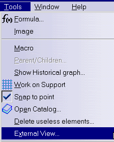 |
Analyzing in "Generative Part Design" (GPS) Workbench Solid Geometry
Designed in Part Design (PRT)


| A 3D OCTREE mesh Part is automatically created. | |
| This mesh part will generate tetrahedron elements. Those elements can be linear (four nodes) or parabolic (ten nodes). They have three degrees of freedom per node (three translation). | |
| All the preprocessing specifications (Loads, Restraints, Masses) will be applied to the Part Body geometry. |
What Type of Hypotheses are Used for Analysis?You will find here below three types of hypotheses used when working in Analysis workbench.
For static case solutions, one can say that:
|
About the Products Available in Analysis Workbench...
|
|
|
|
|
|
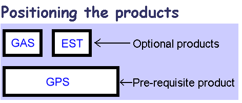
GP1: Generative Part Structural Analysis (P1) GPS: Generative Part Structural Analysis (P2) Addresses transparent and automatic stress and vibration analysis for parts, integrating simulation and design specifications, with the core application of V5 analysis. EST: ELFINI Structural Analysis (P2) Performs advanced pre, post processing and solving with complementary analysis options.
|
|
|
GAS: Generative Assembly Structural Analysis (P2) Addresses transparent, integrated and automatic stress and vibration analysis for assemblies of parts integrating simulation and design specifications. |
About Supports ...
|
|||||||
Analysis specifications can be applied to different types of supports:
When the user selects a mechanical feature, the analysis specification is actually applied on the resulting associated geometry. If this geometry is not an authorized geometrical supports (see table below), the user will not be able to select the mechanical feature. For example, selecting a fillet for a Line Force Density will not be allowed because the resulting geometry of a fillet are surfaces while the authorized geometrical entities for Line Force Density are line or edges.
|
|||||||
| To apply a restraint, a load or a connection to one extremity of a beam,
you need to first put the point that were possibly created
at the extremity of this beam, in order to build the wireframe, into the Hide mode. As result,
to apply the above mentioned specifications,
you will select the extremity of the wireframe and not the hidden point
(small cross in the 3D view) as this point is not linked to the mesh.
|
|||||||
| This is summarized in the table below: |
| Analysis Specifications | Supports |
||||||
| Mechanical Feature |
Geometrical Feature |
Analysis Feature | |||||
| Point or Vertex | Curve or Edge | Surface or Face | Body (Solid or Surface) | ||||
| Loads | |||||||
| Pressures | |||||||
| Distributed Force | Virtual part |
||||||
| Moment | Virtual part |
||||||
| Bearing Load | Cylindrical surface |
||||||
| Acceleration | |||||||
| Rotation Force | |||||||
| Line Force Density | |||||||
| Surface Force Density | |||||||
| Body Force | |||||||
| Enforced Displacement | Restraint specification |
||||||
| Creating Temperature Field | |||||||
| Restraints | |||||||
| Clamps | Virtual part |
||||||
| Surface Sliders | |||||||
| Sliders | Virtual part |
||||||
| Sliding Pivots | Virtual part |
||||||
| Ball Joins | Virtual part |
||||||
| Pivots | Virtual part |
||||||
| Advanced Restraints | Virtual part |
||||||
| Mass | |||||||
| Distributed Mass | Virtual part |
||||||
| Line Mass Densities | |||||||
| Surface Mass Densities | |||||||
| Virtual Parts | |||||||
| All | |||||||
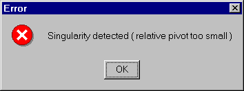
And What If a Singularity Is Detected?If as you launch the computation operation
For example, open the sample31.CATAnalysis document.
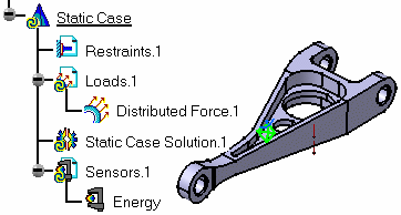
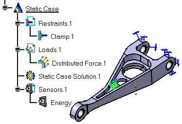
1. Select the Compute icon In addition, an exclamation mark 2. Select the Deformation icon 3. Select the Animate icon 4. In this particular case, you
need to assign a restraint (Clamps
5. Select the Compute icon
|
|
|
|
Improving Performances (SGI)If you installed EST (ELFINI Structural Analysis) product and want to improve performances, it is strongly recommended that you install SCSL SGI product. |
|
|
Improving Performances (Windows NT)To improve performances, download the Intel MKL library from the following intel web site: http://developer.intel.com/software/products/index.htm The Intel MKL library level supported is 5.1.e.
|
|
Warning: Only the last version of Intel MKL can be found on the site, and this version may be an upper level that was tested with CATIA. In this case, you can download it from the Intel FTP site by the following procedure: > ftp download.intel.com > cd /design/perftool/perflibst/mkl/exes/mkl51e You will find in this directory an executable corresponding to the INTEL MKL 5.1e. You just have to execute it to install the version. Then, add to your PATH environment variable, the following string: C:\Program Files\intel\MKL\ia32\bin
|
|
|
Improving Performances on Multi-Processor ComputersOn Windows NT platforms, the ElfiniSolver is multithreaded if more than one processor is found. On SGI machines, you have to specify the number
of processor to be used with the UNIX command: On AIX machines, you may specify the number of
processors to be used with the UNIX command: |
|
|
Miscellaneous
|
|
|
Integration CATIA V5 Analysis / VPMYou will choose PDM destination using a CATIA command, save the docment and then manage the CATAnalysis document using ENOVIA VPM. 1. Load a CAnalysis document in CATIA 2. Save the CATAnalysis document into the VPM database 3. Reload the saved CATAnalysis document from VPM. 4. In CATIA session, create or load a basic assembly including two parts with a constraint. 5. Launch Generative Structural Analysis workbench, create a Static Analysis case and click OK. 6. Apply the desired specifications (Loads and Restraints) and then Compute the CATAnalysis document. This is an example:
Note that the CATAnalysis document points to a CATProduct, a CATAnalysisResults and a CATAnalysisComputation documents. 7. Choose the PDM destination. For this, drag and drop the new setPDMProperties command in any CATIA toolbar. This command can be found in the following menu bar Tools -> Customize Commands Tab and All Commands Categories.
8. Activate the SetPDMProperties command: each pointed document appears in the dialog box. 9. Select the pointed documents you want to save in VPM. For each pointed document, choose the appropriate VPM database environment in Doc Env (See your VPM database administrator).
|
| when saving Assemblies containing applicative data (Such as Analysis Connections), be sure to have the Publication exposed option selected in the Storage Mode box. | |
|
10. Saving the documents from CATIA into VPM and reload the CATAnalysis from VPM. 11. Launch
a VPM session.
12. Launch a Save in CATIA session. For this, select File -> Save all in the menu bar. 13. Refresh the view in VPM. Newly created VPM Parts and documents now appear in VPM window.
14. Close the current CATAnalysis document in CATIA. 15. Open your saved CATAnalysis document from VPM (use double click or Open) The previously saved CATAnalysis document is loaded in CATIA, updated and appears with the corresponding results if any.
|
