Chamfer
| Chamfering consists in removing or adding a flat section from a selected edge to create a beveled surface between the two original faces common to that edge. You obtain a chamfer by propagation along one or several edges. | |||
| This task shows how to create two chamfers by selecting two edges. One case illustrates how material is added, the other case shows how material is retrieved. | |||
| Open the Chamfer1.CATPart document. | |||
|
1.
|
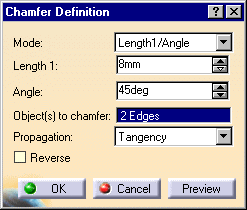
Click the Chamfer icon The Chamfer Definition dialog box appears. The default parameters to be defined are Length1 and Angle. You can change this creation mode and set Length1 and Length2. |
||
| 2. |
Select the edges to be chamfered.
Chamfers can be created by selecting a face: the application chamfers its edges. |
||
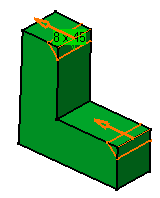
Optionally, click Preview to see the chamfers to be created. |
|||
|
|
|||
| 3. | Keep the default mode: enter a length value and an angle value. | ||
 |
|||
|
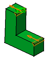
The application previews the chamfers with the given values. |
|||
 |
|||
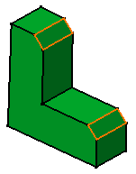
| 4. | Click OK. These are your chamfers: |
 |
|
|
|
|||
