Before You Begin
What is the Active View ? |
||||||||
| The active view is the view from which other views will be generated. This is also the view in which all the modifications will be performed. For instance, all the 2D geometry and dressup elements that will be added to the draft views to be created. | ||||||||
| Open the GenDrafting_part.CATDrawing document. |
|
|||||||
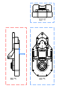
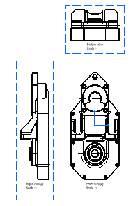
| The active view is framed in
red. The non-active
views are framed in blue. When you create a view, until you click at the desired view location, the view to be created is framed in green. If you click this view, it becomes the active view and is framed in red.
|
||||||||
|
Note that the active view is also underlined in the tree structure. | 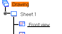
|
||||||
| To make a view active:
1. Double-click the frame of the view. OR 1. Right-click the view to be set active. 2. Select Activate View from the displayed contextual menu. Axes are taken into account on active views. As a result, the frame of an active view will adapt to the elements included in this view. |
 |
|||||||
Defining the Design ModeIn the Product Structure workbench, you can specify that you work either in Visualization mode (Edit -> Representation -> Visualization Mode) or in Design mode (Edit -> Representation -> Design Mode). Accordingly, in the Drafting workbench, the generated views will be either selectable and modifiable or not.
|
||||||||
Defining the View OrientationYou can redefine the reference plane orientation of a view to be created using the available blue arrows. This is the case when generating a front view, an isometric view or when generating views using the wizard. |
||||||||
| Open the GenDrafting_part.CATPart document and start creating a front view. | ||||||||
| 1. Start
creating the view.
2. Click the right or left arrow to visualize the right or left side, respectively. |
 |
|||||||
| 3. Click the bottom arrow to visualize the bottom side. | 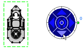 |
|||||||
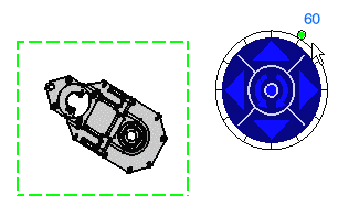
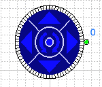
| 4. Click the counterclockwise arrow to rotate the reference plane. | 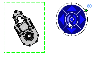 |
|||||||
| 5. Drag the green knob to redefine the rotating angle. The default increment value is 30 degrees. |
 |
|||||||
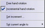
6. You can modify the increment value using the green knob contextual menu. To do this, right-click on the knob and select the desired option from the contextual menu.
|
||||||||
 |
 |
|||||||
|
Free hand rotation: Rotation is not snapped to a given increment but totally free.
Incremental hand rotation: This is the default value: the rotation is snapped to a given increment (from 30 to 30 degrees, between zero and 300).
|
||||||||
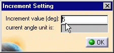
Set increment...: The Increment Setting dialog box displays. 1. Enter the Increment value you need. For example 5 deg (5 degrees).
|
 |
|||||||
| Set current angle to: | 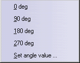 |
|||||||
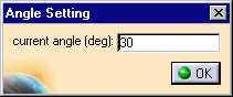
If you select the Set angle value... option, the Angle Setting dialog box appears: 1. Enter the current angle (deg) you need. For example, 30.
|
 |
|||||||
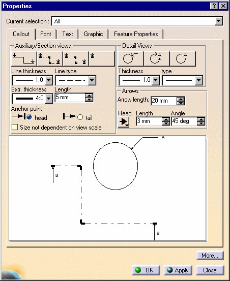
Callout RepresentationYou can choose the callout elements size not to be dependant on the view scale. To do this:
or
|
||||||||
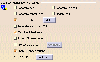
Generated Geometry/Dress Up (Settings)The colors of a part can be automatically generated onto the views. For this, select Tools -> Options from the menu bar, select Mechanical Design -> Drafting at the bottom left of the Options dialog box, Generation tab. Check the 3D colors inheritance option. BE CAREFUL: if the color of the part is white and the 3D colors inheritance option checked, the generated views will result white and therefore not necessarily properly visualized.
|
|||||
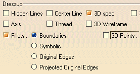
Generated Geometry/Dress Up (Properties)Some geometry is possibly generated (provided you check the desired options using the contextual menu, Properties option, View tab): The graphical properties of generated geometry are kept after you update views. This is also true if you delete one or more elements. |
|||||
|
|||||
ConstraintsConstraints detected when views are generated from the 3D do not appear on the drawing. |
|||||
2D/3D Associativity... On ViewsA generative view results from specifications in a 3D document. This specification corresponds either to the whole document or to a feature in the document. This feature can be:
Any modification applied to the specifications, before the generated view(s) is/are updated, is detected. You can perform an update. You can update all views or a selection of views:
|
|||||
|
|||||
|
|||||
When the update involves several views, a Cancel button is available in this dialog box. This allows you to interrupt the update. The view that is being processed at the time you click this button will be updated (i.e. the update of the current view will finish), and then the update will stop. The subsequent views will not be updated. |
|||||
... After UpdatingUse the following commands to update views:
|
|||||
|
|||||
Updating views means:
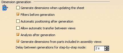
Note that you can restore deleted elements at any time by selecting the Restore Deleted option from the contextual menu and then updating the view. You can either use the Update icon if you modified the 3D part, or key in C:Force Update if you did not modify the 3D part. ... On Generated DimensionsGenerated dimensions are associative with the 3D part constraints on the condition you checked the Generation dimensions when updating the sheet option from the Options dialog box (Tools -> Options -> Mechanical Design -> Drafting -> Generation tab).
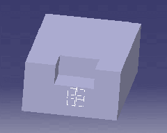
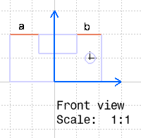
Note that these dimensions will be re-generated in accordance with the other options checked/un-checked in the Options dialog box. ... On ColorWhen you refresh a generated view you have modified, the colors are re-generated with the part geometrical information and you might obtain unexpected results. As an example, if a user creates this part:
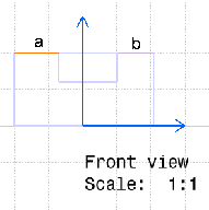
and modify one of the following generated view elements, in this example the line "a" color :
The reason is that the view is refreshed with the part information and a and b lines are considered as the intersection of two planes and not as two different elements of the generative view. ...On Show / No ShowWhen a Part Body is swapped to visible or invisible space, the corresponding generated views are updateable (Update function button activated). |
|||||
|
|
|||||