Creating an Isometric View
| This task will show you how to create an
isometric
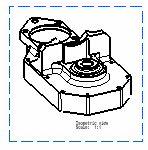
view from a 3D part.
Isometric means "equal measure". To produce an isometric projection, it is necessary to place the object so that its principal edges make equal angles with the plane of projection and are therefore foreshortened equally. Note that an isometric view created from a product can be re-used for generating an exploded view. |
| Before you begin, make sure you customized the following settings:
Grid: View names and scaling factors: 3D colors inheritance |
| Open the GenDrafting_part02.CATPart document. Start creating a new drawing (and this case, create an empty sheet). | |||
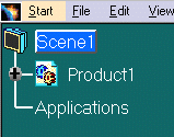
| In a Product Structure context, if you create a front view from a scene of a product, you can directly select the Scene object in the specification tree. You do not necessarily need to select the Product and sub-products any more. |  |
||
| Tile your window vertically to visualize the 3D part and the sheet at the same time. | |||
| 1. Click the Drawing window, and click
the Isometric View icon
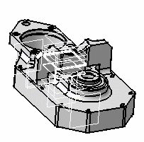
2. Click the 3D part. |
 |
||
| A green frame with the preview of the isometric view to be created, as well as blue manipulators appear. You can re-define the view to be created position using these manipulators: to the bottom, the left, the right, the top, or rotated using a given snapping or according to an edited rotation angle. For more information, see chapter called Before You Begin. |
|
||
| You can insert Bill of Material information into the active view. | |||
|
|||


