Creating Driving Dimensions
| This task shows you how to create dimensions that will drive associated constrained geometry. | ||||||||||
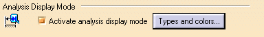
| Go to Tools -> Options ->
Mechanical Design -> Drafting -> Dimension and select
Activate analysis display mode. Then, click the Types and colors
button to define the characteristics that will
be assigned to constrained geometry.
The Types and colors of dimensions dialog box lets you select the color you want to assign to driving dimensions. Select the color shown below, for example.
|
||||||||||
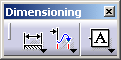
| Click the Dimensions |
 |
|||||||||
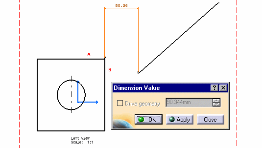
| 1. Double-click the dimension. | 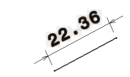 |
|||||||||
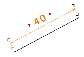
| 2. Modify the dimension via the displayed Dimension Value dialog box. For example, enter 40 millimeter as the new length. This dimension will now drive the geometry. | ||||||||||

|
 |
|||||||||
| If the Drive geometry option is selected, the double-clicked dimension becomes a constraint and behaves as a dimension constraint. | ||||||||||
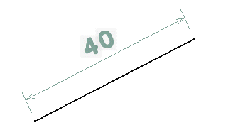
| The geometry is updated in order to reflect the new driving
dimension. Let's call it driven geometry.
In addition, this geometry is assigned the characteristics previously defined in the Types and colors of dimensions dialog box via Tools -> Options. In this particular case, the driving dimension is visualized as follows: |
||||||||||
 |
||||||||||
You cannot create driving dimensions
in the following cases:
|
||||||||||

|