Creating Dimensions
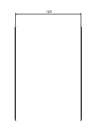
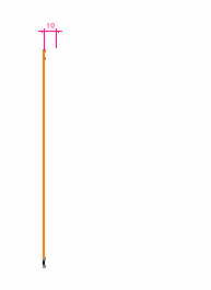
| In this task, you will learn how to create dimensions. When creating dimensions on elements, you can preview the dimensions to be created. | ||||||||||||||
Creating Dimensions |
||||||||||||||
| Open the Brackets_views02.CATDrawing document. | ||||||||||||||
|
1. On the Dimensioning toolbar, click the Dimensions icon.
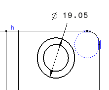
2. Click a first element in the view. For example, a circle. 3. If needed, click a second element in the view. |
 |
|||||||||||||
At this step,
the command options
in the Tools toolbar ( This toolbar is situated at the bottom right of screen. If you cannot see it properly, just undock it. |
||||||||||||||
4. Click the Force
Dimension on element
|
 |
|||||||||||||
| 5.
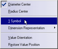
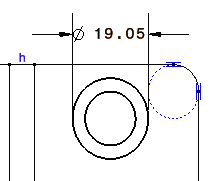
Right-click to access the contextual menu and select 1 symbol.
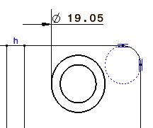
The dimension becomes a one-symbol dimension:
|
||||||||||||||
| During the dimension
creation step, you can switch between one-symbol or two-symbols dimension.
Once the dimension has been created, you must use the Properties
menu to specify whether you want to use one or two symbols. Right-click
the dimension and in the contextual menu, choose Properties. Click
the Dimension Line tab and then check Display Symbol 2
to display two-symbols dimension, or uncheck this option to display
one-symbol dimension.
|
||||||||||||||
| 6. Click in the drawing window to validate the dimension creation. | ||||||||||||||
| 7. Create
another dimension on a line.
|
||||||||||||||
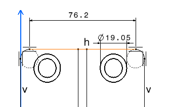
| 8. Select the two dimensions with the Ctrl key (you can move them both). | ||||||||||||||
| 9.
Start creating another dimension: click the command icon
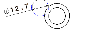
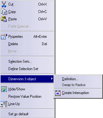
Click in the drawing to validate the creation. 10. Right-click the dimension you just created and in the contextual menu, choose Dimension.3 Object and select Swap to Radius:
The diameter dimension has swapped to radius dimension: 11.
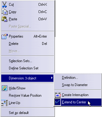
Right-click the dimension again, and in the contextual menu, choose Dimension.3 Object,
and uncheck Extend to Center: the
radius extension line is not extended until the center anymore. |
||||||||||||||
|
||||||||||||||
|
||||||||||||||
PropertiesIf you right-click the dimension before creation, a contextual menu lets you modify the dimension type and value orientation as well as add funnels. Using this contextual menu once the dimension is created, you can also access the Properties options.
|
||||||||||||||
AssociativityIf one parent element of the dimension is deleted or deactivated, as soon as you update
the drawing (either 3D Generative or 2D Interactive drawing), the orphan dimension becomes
purple on the condition you activated the Analysis Display Mode option Ensure that if you key in "c: Force Update" to synchronize the drawing with the 3D, any non-associative dimension will disappear. Colors can be
customized using the Analysis Display Mode option |
||||||||||||||
Driving DimensionsYou can create dimensions that will, by default, drive the geometry. For this:
For more information, refer to Creating Dimension Constraints. |
||||||||||||||
True DimensionsTrue Length dimensions can be created using the True Length Dimensions
option
|
||||||||||||||
| Before using true dimensions make sure that in tools->Options->Associativity on 3D, you have not set only create non-associative dimensions option, to work this functionality must be applied to an associative dimension. | ||||||||||||||
Half-DimensionsYou can create half-dimensions. For this, right-click the dimension as you create it and select the Half-dimension option from the contextual menu.
|
||||||||||||||
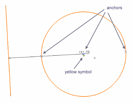
Extension Line AnchorAs you create a dimension between two elements, one of these elements being a circle, you can select the extension line anchor, for this, you can :
|
||||||||||||||
 |
||||||||||||||
You will thus position the extension line:
|
||||||||||||||
| If in Tools -> Options -> Mechanical Design -> Drafting -> Dimension, you have checked Dimension following the mouse option, then to move the extension line anchor you must hold on the crtl key before selecting the yellow symbol (to switch temporarily the option). | ||||||||||||||
|
|
||||||||||||||

