Computing Buckling Solutions
 |
The Compute command is most often
applied to Analysis Case Solutions (which are particular types of objects
sets). In this case, it generates the analysis case solution, along with
partial results for all objects involved in the definition of the Analysis
Case. The primary Buckling Solution Computation result consists of a
set of critical load factors and associated buckling shape vectors, whose
components represent the values of the system degree of freedom for various buckling
modes associated with a given Static Case.
The program can compute simultaneously several Solution objects sets,
with optimal parallel computation whenever applicable.
This capability is only available
with the ELFINI Structural Analysis product  . .
|
 |
Avoid having CATAnalysis documents automatically saved. For
this, go to Tools->Options->General (menu bar) and
de-activate the Automatic save every xx minutes option.
Otherwise, on some models, each computation will be followed by a Save,
thus making temporary data become persistent data.
|
 |
This task shows how to compute a
Buckling Case Solution.
|
 |
You can use the sample29.CATAnalysis
document from the samples directory: you created a Finite Element Model containing
a Buckling Analysis Case. |
 |
1. Select the Buckling Case Solution feature from the specification tree
and then click the Compute icon  . .
The Compute dialog box is displayed.
The combo box allows you to choose between several options for the set
of objects to update:

 | All: all objects defined in the analysis specification tree will be
computed. |
| Mesh Only: the preprocessing parts and connections will
be meshed. The preprocessing data (loads, restraints and so forth)
will be applied onto the mesh. For your information, in case the Mesh
only option was previously activated, you will then be able to
visualize the applied data on the mesh by using the Visualization
on Mesh option (contextual menu). |
| Analysis Case Solution Selection: only a selection of user-specified
Analysis Case Solutions will be computed, with an optimal parallel
computation strategy. |
| Selection by Restraint: only the selected characteristics
will be computed (Properties, Restraints, Loads, Masses). |
The Preview switch allows you to obtain an estimate of the Time and
Memory required to perform the computation, prior to triggering the actual
computation.
2. Select Analysis Case Solution Selection.

In this case, the program will compute the Buckling Case Solution in the
analysis specification tree.
3. Activate the Preview
button and click OK.
The estimates are displayed in the Preview dialog box. You can proceed
with the computation or choose to postpone it.
4. To launch the computation, click Yes.

The Progress Bar dialog box provides a series of status messages (Meshing,
Factorization, Solution) that inform you of the
degree of advancement of the computation process.
The Buckling Analysis Solution is computed and can be visualized.
Upon successful completion of the computation, the FE mesh
is visualized on your part, and the status of all objects in the analysis
features tree up to the Buckling Case Solution objects set is changed to
valid. You can now:
| analyze the report of the computation |
| visualize images for various results |

|
 |
Products Available in
Analysis Workbench
The ELFINI Structural Analysis product offers the following
additional feature:
| If several Buckling Analysis Cases have been defined, you can compute
them simultaneously by following the same procedure. |
|
To display CPU time and memory
requirement estimates prior to launching any computations, activate the
Estimates switch in the Update dialog box. |
| The status and results of
intermediate pre-processor computations necessary to perform this
translation are reported in HTML format. For more detail see the basic
global Report capability. |
|
The Definition parameters of an Analysis Case,
(available, in the ELFINI Structural Analysis product, in the New
Case dialog box at the time of a Case Insertion) cannot be modified once
the Case has been created. These parameters must not be confused with the Computation
parameters of a Case Solution, which are proposed by default at creation,
and are editable afterwards. |
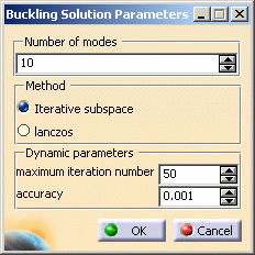
To edit the default values of the Computation parameters of a Case
Solution, double-click the Solution objects set in the analysis features
tree (or right-click, then click .Object -> Definition
) to display the Definition par... dialog box.
The Buckling Solution Parameters dialog box contains the following parameters which can all be modified in the dialog
box:
- Number of modes
- Method (Iterative subspace or lanczos)
- Dynamic parameters (Maximum iteration number
and Accuracy)
|
|
|
The ELFINI Structural
Analysis product offers the following additional features with a right
mouse click (key 3):
|
on a Static Case Solution objects set:
 |
Generate Image: allows to generate the various images available
along with the Static Solution objects set. The image can be edited to
include part or all of the options available.
Right-click the Buckling Case object and then click the Generate Image
option from the displayed contextual menu
(on the condition you previously computed a solution using the Compute icon ).

The Image Choice dialog box is displayed. You can select images by
clicking them in the list.
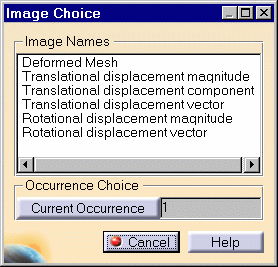
Since a Buckling solution is a multi-occurrence
solution, you can select the buckling mode that will be displayed by
clicking the Current Occurrence button.
The resulting images sequence is obtained by superposition.
|
|
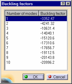
Report: the global status and results of all computations are
reported in HTML format.
Click the Basic Analysis  Report icon
(on the condition you previously computed a solution using the Compute icon ).
Report icon
(on the condition you previously computed a solution using the Compute icon ).
The .html partial report file is displayed. It contains a summary of
the buckling computation results.

|
|
|

|
|