 Generating CGR Views
| This task will show you how to
generate a view using the CGR format (CATIA
Graphical Representation). CGR corresponds to a data format containing a graphical representation of the geometry only, which is available with the Visualization mode (as opposed to the exact geometry, which is available with the Design mode). With CGR, only the external appearance of the component is used and displayed; the geometry is not available. The corresponding .cgr file, if it exists, is inserted from the cache system. CGR-generated views are not as high in quality as non-CGR views, but they consume much less memory during the generation. This may be useful when you deal with sophisticated products or assemblies involving large amounts of data. Using CGR to generate views offers the following advantages:
|
|||||||||||
| Activate the Work with
the cache system setting. Open the Gun_Body.CATProduct
document. The document is automatically open in Visualization mode.
For more information, see Using the Cache Memory in the Infrastructure User's Guide
and Visualization
mode in the Product Structure User's Guide.
|
|||||||||||
| 1. Select the Tools -> Options command.
The Options dialog box appears.
2. Click Mechanical Design -> Drafting in the list of objects to the left of the Options dialog box. 3. Select the Generation tab. 4. In the Geometry generation / Dress up area, check the Generate View from CGR box. |
|||||||||||
 |
|||||||||||
| As you can notice, all other options on the Generation tab
have become unavailable,
except for Hidden lines.
The Only generate parts larger than option has become available. This lets you specify that you only want to generate parts which are larger than a certain size. Leave the option unselected.
|
|||||||||||
5. From the open CATProduct document, you can create either one
of the following view types:
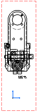
Create a front view, for instance. The view is generated, based on the CGR format.
|
|||||||||||
6. With the Generate View from CGR
box checked in the Options dialog box, you can also create either one of the following view
types:
|
|||||||||||
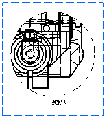
For the purpose of this exercise, you will create one of the above-listed view types from a CGR-generated view. However, with the Generate View from CGR box checked, you can also create any of these view types from non-CGR views. Create a quick detail view, for instance. The view is generated, based on the CGR format.
|
|||||||||||
When the Generate View from CGR box is checked in the Options dialog
box, you
cannot create the following view types:
|
|||||||||||
| 7. If you
need, you can always turn a CGR view into an exact view and vice-versa. To
do so, right-click the front view and select Properties from
the contextual menu. The Properties dialog box is displayed.
|
|||||||||||
| 8. Click
the View tab and select Exact from the Generation
Mode area. The view is turned into an exact view and the geometry becomes
available.
|
|||||||||||
|
|
|
||||||||||
|
|||||||||||

