Creating a Front View
| This task will show you how to create a front view
on the sheet previously defined and from the 3D part you previously opened.
|
|||||
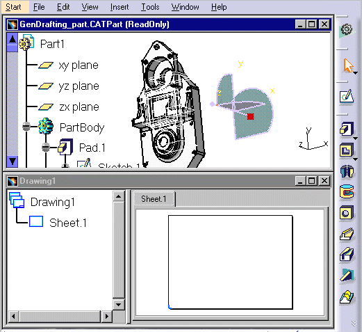
| At this step, we strongly advise that you tile screen horizontally . For this, go to Window -> Tile Horizontally
options from the menu bar.
If you do not want to have the specification tree displayed, press the PF3 key.
|
|||||
| 1. | Click the Drawing window, and click the Front
View icon |
 |
|||
 |
|||||
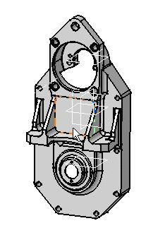
| 2. | Select the desired planar surface of the 3D part you opened, from the 3D Part viewer. |
 |
|||
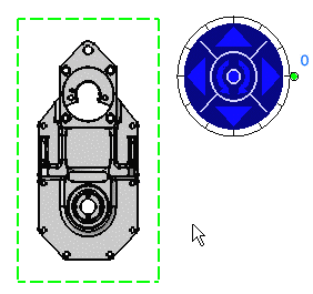
Blue arrows and a green frame including a preview of the view to be created appear on the sheet. These frame and arrows allow defining the location and orientation of the view to be created.
|
|||||
| 3. |
Click on the drawing sheet or at the center of the blue manipulator to generate the view. As long as you see the green frame, you can define the frame position using the blue manipulators: top, bottom, left, right or rotated according to a given snapping, or else according to an edited rotation angle. |
|
|||
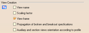
In the Generative Drafting workbench, the view name, scaling factor and view frame are set by default. Throughout this documentation, we decided not to display view names and scaling factors. For this: |
|||||
Go to Tools->Options->Mechanical Design->Drafting option (Layout tab) and un-check the View name and Scaling factor options. |
|||||
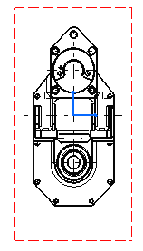
The front view is created. |
|
||||
| From now on, you will work on the created sheet unless you define a new sheet. | |||||
|
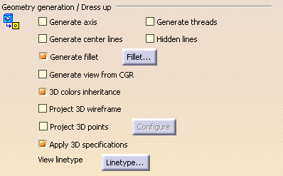
By default, a number of elements can
be visualized on generated views. If needed, go to Tools->Options
-> Mechanical Design -> Drafting option (Generation tab)
to change this by un-checking the required options.
|
||||
